
Measuring the speed of a rotating object is a common requirement. Knowing the speed of table and ceiling fans, as well as kitchen appliances such as mixers and grinders, can often be useful. However, fan speed controls only increase or decrease the speed and do not indicate the actual RPM (rotations per minute).
Cars, other vehicles, and even powered two-wheelers include a speedometer in front of the driver. This displays speed in kilometres per hour (km/hr), which is the commonly used unit. Earlier systems often expressed speed in miles per hour.
POC Video Tutorial
A tachometer device for bicycles can also be developed using an Arduino board based on the ATmega328P. Bicycle speedometers are useful for children who wish to monitor their speed while riding or racing.

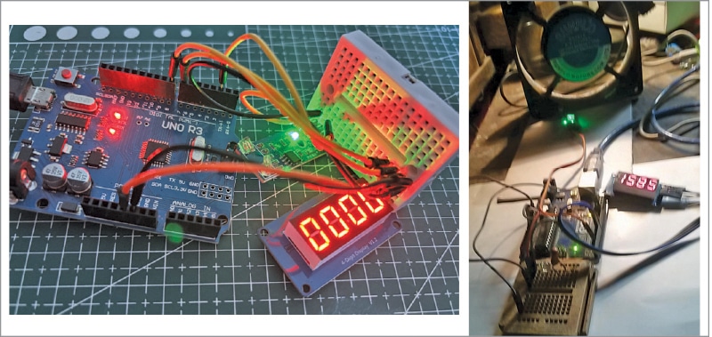
The TM1637 four-digit LED display module is a compact and convenient device that shows bright numerical output using only a four-wire connection, as seen in the prototype. Fig. 1 shows the EFY Lab prototype (left) and the author’s prototype used for measuring fan rotation (right).
For display, a TM1637-based LED segment display is used, and an IR proximity sensor is used for speed measurement. The components required to build this device are listed in the Bill of Materials table.
| Bill Of Materials | |
| Components | Quantity |
| Arduino Uno | 1 |
| TM1637-based LED segment display | 1 |
| IR sensor module | 1 |
| A small rod | 1 |
| Assembly item | As required |
| Jumper wires | As required |
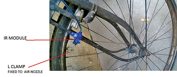
IR module, Arduino Uno, and TM1637 display
The IR module consists of an infrared LED and a photodiode that detect reflected infrared light from nearby objects and produce digital pulses. These pulses can be counted to detect motion, speed, or object presence.
The Arduino Uno is a microcontroller board based on the ATmega328P that processes signals from sensors and controls other devices.
The TM1637 4-digit 7-segment display is a compact digital display module that shows numbers such as speed, time, or counts using only two communication pins.
Together, these components form a simple measurement system. Fig. 2 shows the Arduino Uno, TM1637 display, and the IR module used in this project.
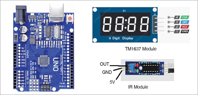
The three pins of the IR module are Vcc (5V), ground, and output. When a 5V supply is applied to the module, the IR LED emits infrared rays. The power status is indicated by a miniature green LED on the PCB.
The photodetector receives reflected infrared rays. If a reflecting surface is present at a distance of about 2.5cm to 5cm, the reflected signal is amplified, which lights another on-board miniature green LED. Thus, one mini green LED indicates power on, while the other indicates reflection from a target.
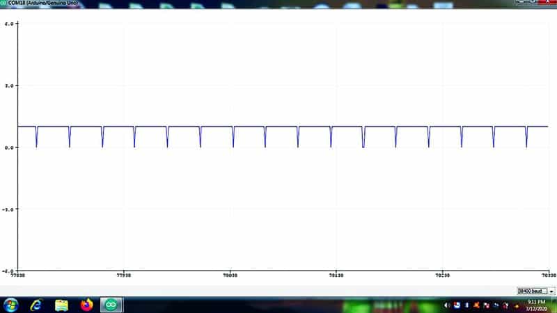
As shown in the author’s prototype (see the right side of Fig. 1), when the IR module is placed close to the fan blades without touching them, the rotating blades reflect infrared light back to the sensor. This produces a series of pulses at the output pin as the fan runs. These pulses are illustrated in Fig. 3.
Circuit diagram
Fig. 4 shows the circuit diagram of the tachometer device. It is built around the Arduino Uno (MOD1), TM1637-based LED segment display (MOD2), and IR sensor module (MOD3), along with a few other components.
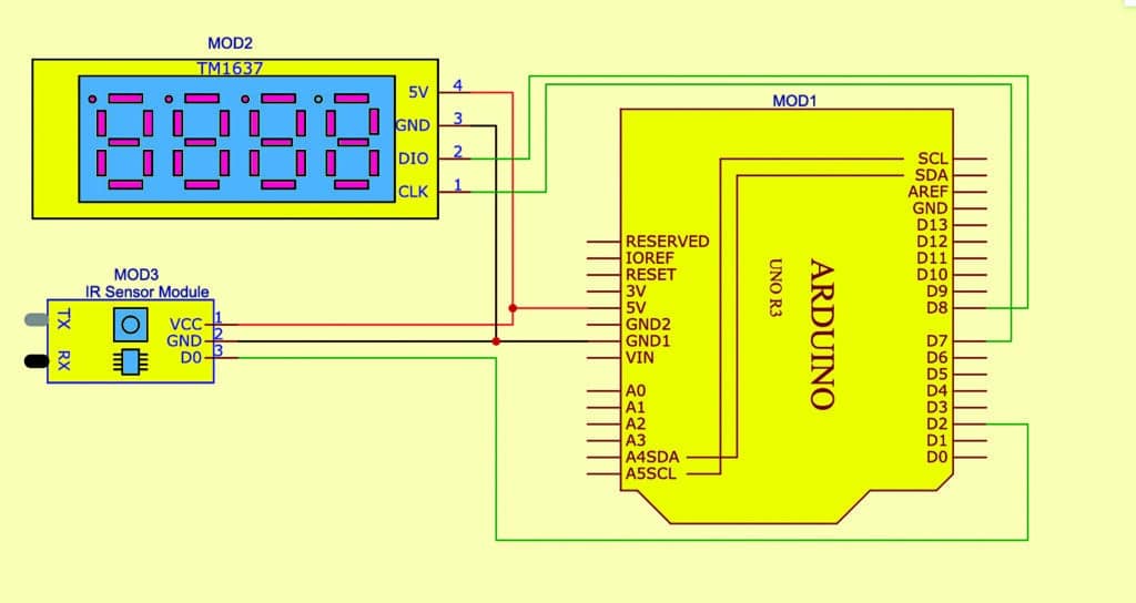
The connections to the IR module are Vcc, ground, and the pulse output pin D0. The Vcc and ground are supplied from the Arduino board.

Sorry! You cannot read this post further, as this is for EFY PRIME subscribers only.