

Decorative lighting has become quite popular, with options such as LED surface panels, strip lights, COB lights, spotlights, and profile lights that are widely used in residential and other interior designing. Lighting choices vary based on client needs, offering flexibility to both homeowners and the designers. This smart lighting controller serves as a chasing panel solution to set the mood, create ambience, and elevate the overall feel of a space.
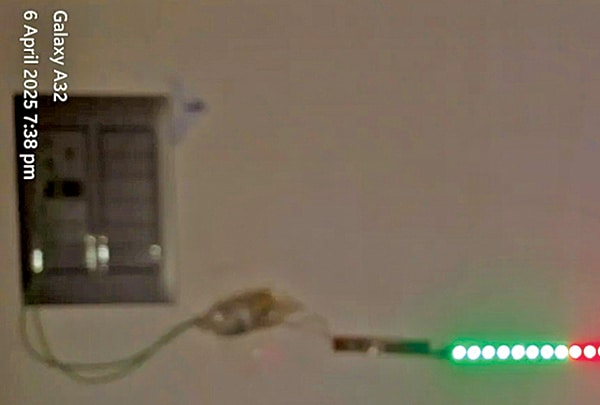
The controller integrates a microcontroller, a radar motion sensor, and a NeoPixel LED strip. When motion is detected, the LED strip gradually switches on, lighting each LED sequentially in a warm colour. As movement continues, the strip transitions through a series of warm hues—such as orange, gold, and pink—changing every second to maintain a cosy atmosphere. If no motion is detected for 10 seconds, the LEDs fade out in reverse order, creating a smooth shutdown effect. This makes the device ideal for hallways, bedroom lighting, or any decorative setup that responds to movement.
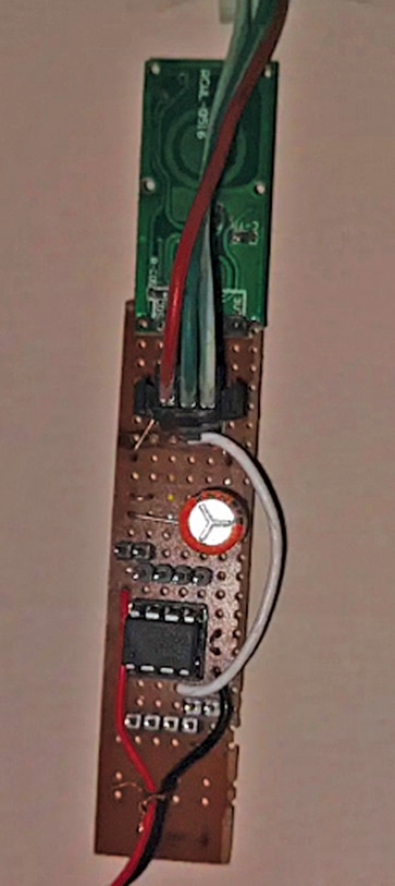
Fig. 1 shows the prototype on a general-purpose PCB, with the ATtiny85 microcontroller placed in its socket and wired to the radar sensor. All components required to build the controller are listed in the Bill of Materials table.
| Bill Of Materials | |
| Components | Quantity |
| Neopixel LED array LED1 and LED2 (each 1 metre) | 2 metres |
| ATtiny85 (IC1) | 1 |
| RCWL0516 microwave radar (S1) | 1 |
| MCU programmer (Arduino Uno) | 1 |
| Small general-purpose PCB | 1 |
| 5V power supply | 1 |
| Flexible wires | As needed |
As the ATtiny microcontroller requires programming and the bare IC does not feature an onboard programmer, a separate programmer is needed. Alternatively, an Arduino Uno board can serve as the programmer. In this case, the Arduino Uno has been used to program the ATtiny85. However, it is also possible to skip these steps and use the Arduino Uno board directly as the main controller instead of the ATtiny85. The ATtiny85 was selected due to its compact size and suitability for embedded lighting control.
Circuit and working
Fig. 2 shows the circuit diagram of the smart LED lighting controller. The circuit consists of NeoPixel LEDs, an ATtiny85 microcontroller, and an RCWL microwave sensor. The system can be powered by any 5V, 1A SMPS (such as a mobile charger), which is suitable for a 1-metre strip with 60 LEDs, or adjusted based on the current requirement of the LED strip, calculated at 60mA per LED at 5V. The power requirement in watts can be calculated using the following relationship:
OOPS! THIS IS EFY PRIME CONTENT…
which means that you need to be an EFY PRIME subscriber to read it.
EFY PRIME content is our best content. Hence, you need to make a small investment to access all of our content including EFY Prime content.
If you’re already an EFY PRIME member, feel free to login below.
Else, CLICK HERE to invest in an EFY Prime account and become our VIP customer who can access all our content, and that too without the clutter of ads!
BENEFITS OF EFY PRIME MEMBERSHIP:
(1) Zero Clutter AD free experience
(2) Super-fast user experience
(3) Focussed reading experience with no distractions
(4) Access to all our content including our Best-of-Best which is EFY Prime