

Advanced Satellite for Telemetry and Remote Access (ASTRA) is a CubeSat model designed to offer hands-on experience in satellite technology. It serves as a practical platform for learning and innovation in space systems.
While conventional education often leans heavily on theory, it can leave students underprepared for real world engineering challenges. ASTRA addresses this by allowing learners to apply classroom concepts through the design, construction, and operation of a working satellite model. The result is meaningful exposure to satellite systems and embedded technologies. The required components are listed in the Bill of Materials table.
| Bill of Materials | ||
| Components | Quantity | Details |
| Dotted PCB/perf board | 1 | Baseboard |
| ESP32 development board | 1 | Controller |
| MPU6050 gyro sensor module | 1 | IMU |
| NEO-6M GPS module | 1 | Positioning |
| INA219 current sensor | 1 | Monitoring |
| Buck converter | 2 | Regulator |
| Screw terminals | 4 | Connectors |
| Pin headers | 15 | Interface |
| Pin sockets | 30 | Mounting |
| 18650 batteries | 3 | Power |
| 3D printing files for CubeSat frame |
1 | Structure |
| BMS board | 1 | Battery management |
Circuit and working
Fig. 1 shows the circuit diagram of the CubeSat model. The setup is primarily based on the ESP32 development board, the MPU-6050 sensor module, the NEO-6M GPS module, the INA219 current sensor, and supporting components.
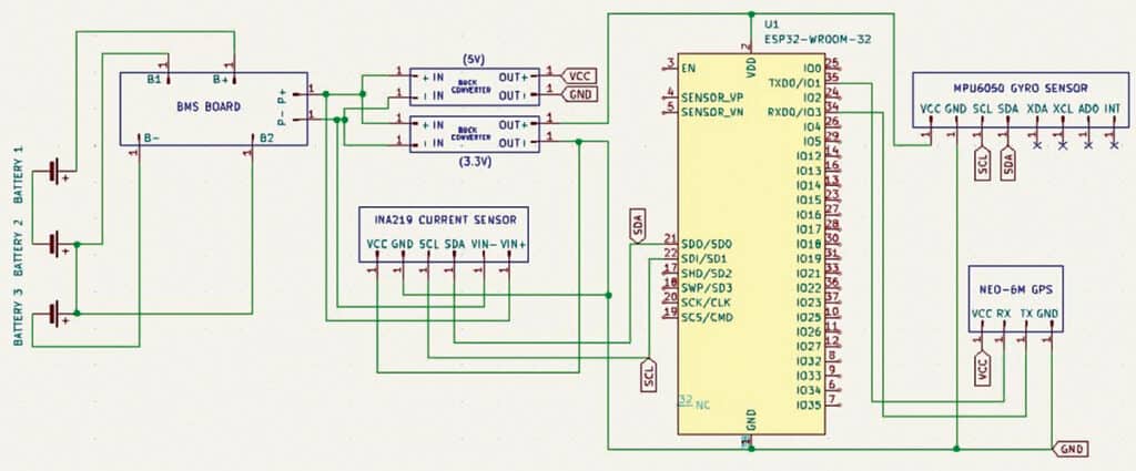
An onboard computer (OBC) is included to manage the satellite’s power system and to transmit real-time data, such as current, voltage, load, and power consumption, via a Wi-Fi network. The source code can be modified to transmit and receive additional payload data, including UV detection, GPS coordinates, and IMU sensor readings.
In addition to the current sensor, the model includes an MPU6050 gyro sensor for orientation and a GPS module for location data. However, these data are not currently transmitted to the hosted webpage. Test code is provided for these modules, which enables viewing their output on the serial monitor. The main transmitter code requires modification to enable remote transmission of the payload data to the webpage.
A battery management system module supports the power system. Its output connects to a buck converter, which supplies power to the OBC. A second buck converter powers additional payloads. The INA219 current sensor and MPU6050 are both connected to the ESP32’s I2C bus, while the GPS module connects via the ESP32’s USART pins.
Software
Three source code files are included. The main file hosts a webpage and sends real-time power readings to it. The remaining two are test files that display data from the GPS and MPU6050 sensors via the serial monitor.
OOPS! THIS IS EFY PRIME CONTENT…
which means that you need to be an EFY PRIME subscriber to read it.
EFY PRIME content is our best content. Hence, you need to make a small investment to access all of our content including EFY Prime content.
If you’re already an EFY PRIME member, feel free to login below.
Else, CLICK HERE to invest in an EFY Prime account and become our VIP customer who can access all our content, and that too without the clutter of ads!
BENEFITS OF EFY PRIME MEMBERSHIP:
(1) Zero Clutter AD free experience
(2) Super-fast user experience
(3) Focussed reading experience with no distractions
(4) Access to all our content including our Best-of-Best which is EFY Prime