
Imagine tracking power-line voltage, frequency, current draw, and appliance power consumption through a smart switch plug. Real-time data is continuously logged to a database, enabling instant energy-use calculation, billing estimation, and live device control.
The system integrates with popular AI assistants and smart speakers, including Alexa, Google Home, Google Assistant, Apple HomeKit, and the ESP RainMaker app. Appliances can be operated through voice commands, automation rules, or a touch-based switchboard.
ESP RainMaker is an end-user platform built for production-ready IoT devices. It enables firmware development and complete IoT solution design for large-scale deployment. Core features include device monitoring, over-the-air firmware updates, and centralised device management, streamlining the transition from prototype to production and market launch. The platform also manages Wi-Fi provisioning, device onboarding, and firmware control, similar to commercial smart plugs and bulbs. A dedicated home application provides a unified interface for parameter monitoring, remote appliance control, and mesh-network creation to ensure reliable connectivity.

Dedicated current and voltage sensors measure electrical parameters accurately. By combining data from both sensors, real-time energy consumption is calculated. Based on this information, advanced features such as over-voltage and over-current protection, automatic low-power mode, and energy-usage-based automation are implemented.
For example, the system can automatically turn off high-power appliances when the electricity bill reaches a predefined limit, or shut down all connected loads if total consumption exceeds a specified threshold within a billing cycle. Such tightly integrated, energy-aware automation was not feasible in earlier designs.
Conventional solutions either provide IoT-based control for lights and fans or use separate energy meters for billing, often requiring independent touch switches and control units. In contrast, this design integrates smart switching, energy monitoring, billing intelligence, and automation into a single compact device.
This integrated approach offers flexibility for home automation, real-time monitoring, intelligent switching, and AI-assistant-based voice control. Earlier implementations used ESP RainMaker primarily to support IoT switches with Alexa and Google Assistant compatibility. In this system, the same RainMaker platform is extended by integrating current and voltage sensing with a smart billing mechanism, resulting in a comprehensive, production-ready energy-management solution.
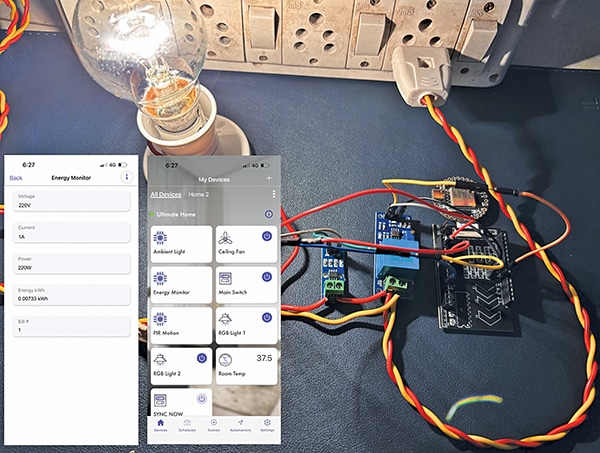
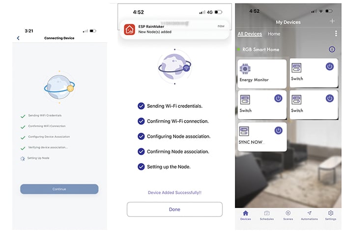
Fig. 1 shows the ESP RainMaker app interface with an integrated smart home dashboard and real-time energy monitoring. The left screen displays multiple smart switches and an energy-monitor device, while the right screen presents live electrical parameters such as voltage, current, power, energy consumption, and estimated electricity bill. Fig. 2 shows the connected device with the RainMaker app displaying power and energy consumption.

To build the system, the required components are listed in the Bill of Materials table.
| Bill Of Materials | ||
| Item | Name | Quantity |
| IndusBoard coin/ESP32 S3 board | U1 | 1 |
| ACS712 current sensor | U2 | 1 |
| ZMPT101B voltage sensor | U3 | 3 |
| Relay module | U4 | 2 |
| 5V DC power adaptor | U5 | 1 |
| Resistor 2kΩ (R1) | R1 | 1 |
| Resistor 10kΩ (R2) | R2 | 1 |
Calibration circuit
Fig. 3 shows the calibration circuit. The relay controls the appliance on or off. In this design, a single relay is used. The ACS current sensor measures AC current and frequency, while the ZMPT101B module performs voltage measurement.
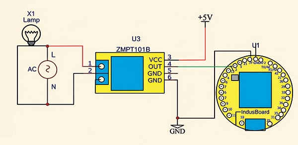
Additional relays can be added to control more appliances using available I/O pins. Since the sensor operates at 5V logic and the controller uses 3.3V logic, a voltage divider is required to reduce the signal level. A 2kΩ and 10kΩ resistor divider is used for this purpose.
Calibration of sensor
First, the ZMPT101B voltage sensor must be calibrated. Connect the sensor to the IndusBoard Coin (refer to Fig. 3) and upload the calibration code.
//--------------------------------------
void setup() {
Serial.begin(115200);
}
void loop() {
int raw = analogRead(3); // Your
pinSerial.println(raw);
delay(1); // Fast for Serial Plotter
}
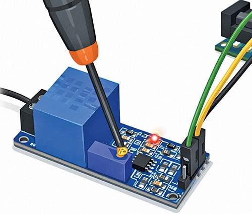
//--------------------------------------Next, open the serial plotter and rotate the potentiometer using a screwdriver, as shown in Fig. 4, until a clean sine waveform appears. Fig. 5 shows the sine waveform observed on the serial monitor during adjustment.

Voltmeter sensor testing code
After a clean sine wave is obtained, the full waveform becomes visible on the plotter without clipping. The voltage can then be measured using the ZMPT101B example code. If a multimeter is available, the sensor reading should be compared with the multimeter value. Any difference can be corrected through further calibration by adjusting the sensitivity value in the code.
#include
#define SENSITIVITY 500.0f
// ZMPT101B sensor output connected to
analog pin A0
// and the voltage source frequency is
50 Hz.
ZMPT101B voltageSensor(3, 50.0);
void setup() {
Serial.begin(115200);
// Change the sensitivity value based on
value you got from the calibrate
// example.
voltageSensor.setSensitivity(SENSITIVITY);
}
void loop() {
// read the voltage and then print via
Serial.
float voltage = voltageSensor.
getRmsVoltage();
Serial.print(voltage);
Serial.print(“V”);
Serial.println(“-----”);
delay(1000);
}
Circuit and working
After calibration, complete the circuit as shown in Fig. 6. The system is built around the IndusBoard (U1), ACS712 current sensor (U2), ZMPT101B voltage sensor (U3), a 5V relay module (U4), and supporting components. A 5V DC power adaptor supplies the circuit.
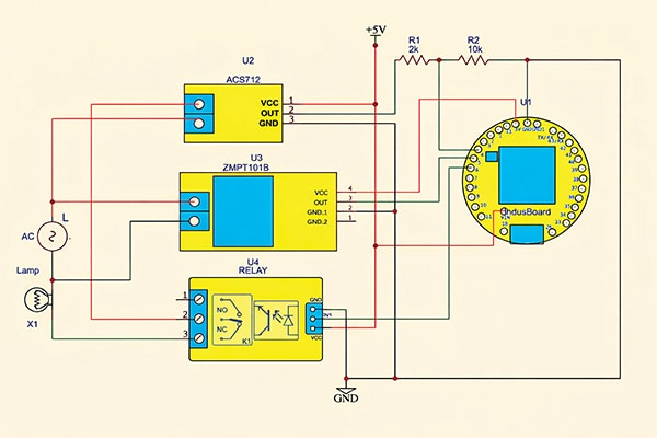
The current sensor output connects to the IndusBoard via a voltage divider circuit. The ZMPT101B is powered directly from the board, and its output pin connects to pin 5 or another pin as defined in the code. The load is connected between the current sensor’s live output and the AC mains neutral.
The ACS712 operates at 5V logic, while the IndusBoard uses 3.3V logic. Therefore, a voltage-divider circuit with two resistors is required to reduce the signal level. During testing, resistor values of 10kΩ and 2kΩ were used. The code may be adjusted according to the selected resistor ratio.
The divider is configured as shown in the circuit diagram. The sensor can be powered using either a 5V external adaptor or the 5V/Vin pin when powered through USB. The ground is shared, and the midpoint of the divider connects to an ADC-capable I/O pin on the board (pin 4 in this configuration).
EFY note: If the ZMPT101B voltage sensor has not been calibrated, refer to the calibration section to ensure accurate voltage readings.
Software
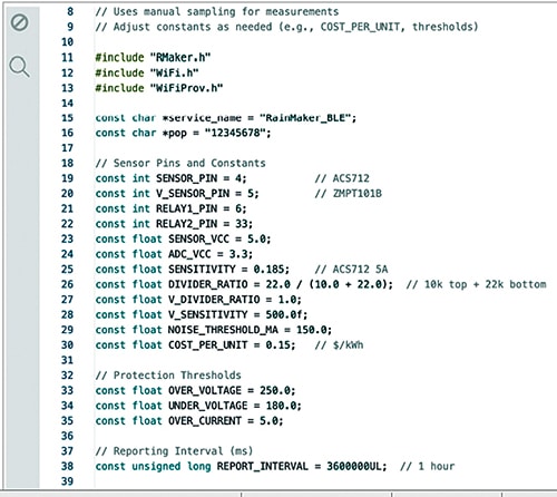
Within the firmware, the sensor pins are configured and the current sensor type (5A, 10A, or 30A) is selected. The voltage sensor pin and calibration parameters are also defined. Protection features are included to set over-voltage, under-voltage, and over-current thresholds, safeguarding the device and connected loads.
A provisioning mechanism connects the device to a Wi-Fi network for the end user. A dedicated system button enables manual data updates and synchronisation. The button can be triggered through the app interface or via Alexa or other AI assistants by requesting a device sync. Otherwise, the application automatically synchronises data at one-hour intervals, which can be adjusted as required. After completing configuration and calibration, upload the code to the board. Fig. 7 shows the RainMaker code snippet with calibration parameters and sensor pin configuration.
Provisoning the device
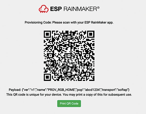
After uploading the firmware, open the serial monitor. A link for generating the provisioning QR code is displayed. Copy and paste this link into a web browser to generate the QR code, then save and download it.
For production deployment, the QR code should be printed on the manual or packaging and supplied to the customer. The device can then be provisioned by scanning the QR code. Fig. 8 shows the generated provisioning code.
Configuring the app
Download the RainMaker app from the App Store or Play Store and sign in using an email or iCloud account. Tap the plus (+) icon and scan the saved QR code. Once connected to the device’s Wi-Fi network, the app prompts selection of the home network and entry of the password.
Adding device to AI assistant
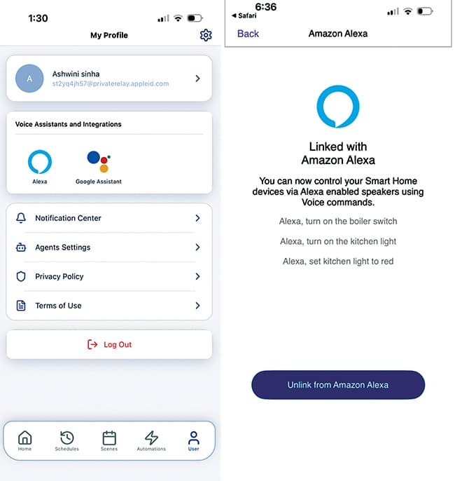
The device supports integration with Alexa, Google Assistant, and Apple Home. After linking, appliances can be controlled through voice commands or automated using sensor data and other connected devices.
To enable integration, open User Options in the RainMaker app and select the preferred assistant. Follow the on-screen instructions to complete the linking process. After successful linking, the device appears automatically in the assistant’s device list, where voice commands and automation routines can be configured.
Testing
Testing the smart energy meter with Alexa is straightforward. Issuing the command “Alexa, turn on Sync on the Energy Meter” updates the device and sends the latest sensor data to the cloud. Queries such as “What is my electricity bill?” or “How much power is the appliance using?” return real-time responses.
Alternatively, the RainMaker Home app allows manual synchronisation using the Sync button. Detailed readings, including voltage, current, power consumption, total energy (kWh), and estimated billing, are available in the Energy Monitor section.
The two relay switches function as standard on/off controls, enabling remote operation of connected appliances. The meter also provides built-in protection and seamless voice control through Alexa, Google Home, or Apple HomeKit. The left side of Fig. 1 illustrates overall device control and monitoring, while its right side displays real-time voltage, current, power, energy consumption (kWh), and estimated billing data.
Ashwini Kumar Sinha, an IoT and AI enthusiast, is Tech Journalist at EFY.