Here we are designing a very small, tiny CAN network sensor that can be attached to any vehicle. It detects motion, accidents, and all vehicle activities in real time. It can also be modified to act like a black box for the vehicle, storing all activity logs. This is not just for cars — it can be used in ships, motorboats, drones, rockets, and almost any area where CAN bus is already used. It can be programmed to add more sensors and send their data to the CAN bus network.
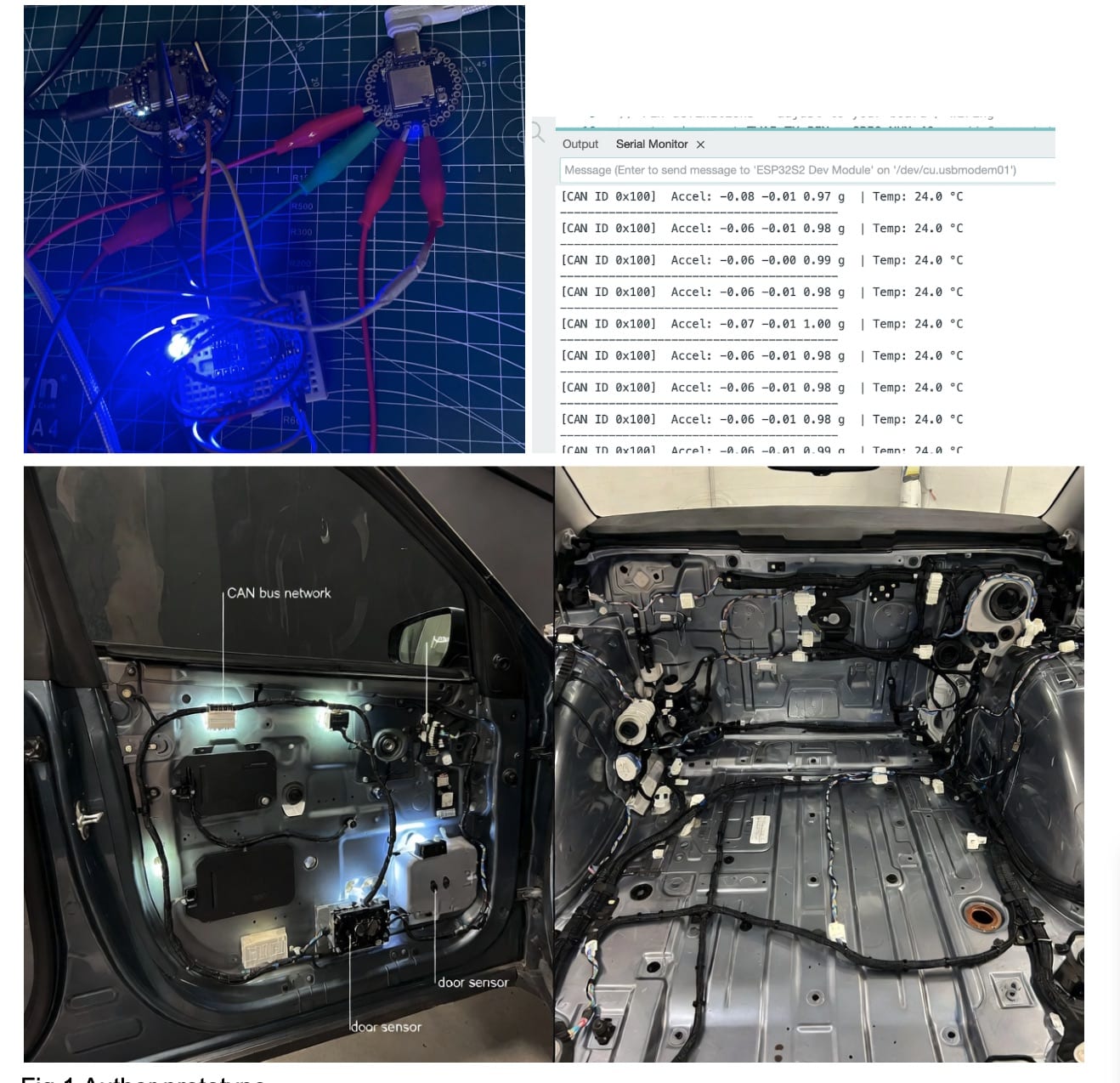
In the current design, we are using the IndusBoard Coin, which is super small (only about 3 cm) and has a built-in IMU, temperature sensor, and many other features, plus support for an internal CAN bus driver. This helps keep our design extremely compact and lightweight — perfect for attaching to light drones, rockets, cars, and many other places where small CAN sensors are needed.
Our system uses its internal IMU and sensors to detect the vehicle’s activity, orientation, and events. It can identify time, accidents, whether the vehicle rolled over, collisions, braking, speed, acceleration, deceleration, etc., and sends all this data to the CAN bus network — to the engine ECU or the vehicle’s main board.


Bill of Materials
| ID | Name | Designator | Quantity |
| 1 | IndusBoard Coin | U! | 2 |
| 4 | CAN Bus TJA1050 Module | U2 , U3 | 2 |
| 5 | OBD Port Connector | U8 | 1 |
| 6 | Twisted Connector Wires | 1 | |
| 8 | USB-C Cable | 1 |
Before design, let’s understand the main parts:
What is CAN Bus?
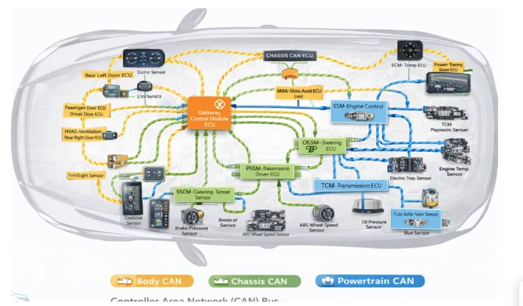
Unlike many other communication peripherals, CAN Bus does not require separate wiring for each device. Instead, all electronic control units (ECUs)—such as the engine controller, brakes, dashboard, and sensors—are connected using just two twisted wires. These wires allow every ECU to “listen” and “talk” on the same network.
In a multi-master configuration, all ECUs share the CAN Bus, meaning any ECU can take control of the bus at any time and broadcast messages, such as sensor data or control commands, to the entire system. Every ECU receives these messages and independently decides whether to process or ignore them based on the message identifier.
The physical layer of the CAN Bus is remarkably simple, consisting of only two twisted wires: CAN High and CAN Low. Twisting the pair helps cancel electromagnetic interference, ensuring reliable communication even in the electrically noisy environment of a vehicle.
Data transmission works by varying the voltage levels on these two wires. When the bus is idle or transmitting a logic 1 (recessive state), both CAN High and CAN Low sit at approximately 2.5 V, producing no voltage difference. When a node transmits a logic 0 (dominant state), CAN High rises to about 3.5 V while CAN Low drops to around 1.5 V, creating a 2-volt differential.
This dominant state signals to all other nodes that the bus is in use, forcing them to wait until the transmission is complete before attempting to send their own messages. This simple yet robust signaling scheme enables multiple devices to safely and efficiently share the same two wires.
OBD2 Port – The Diagnostic Connector in Vehicles
Almost every car made after 1996 has an OBD2 port (On-Board Diagnostics II).
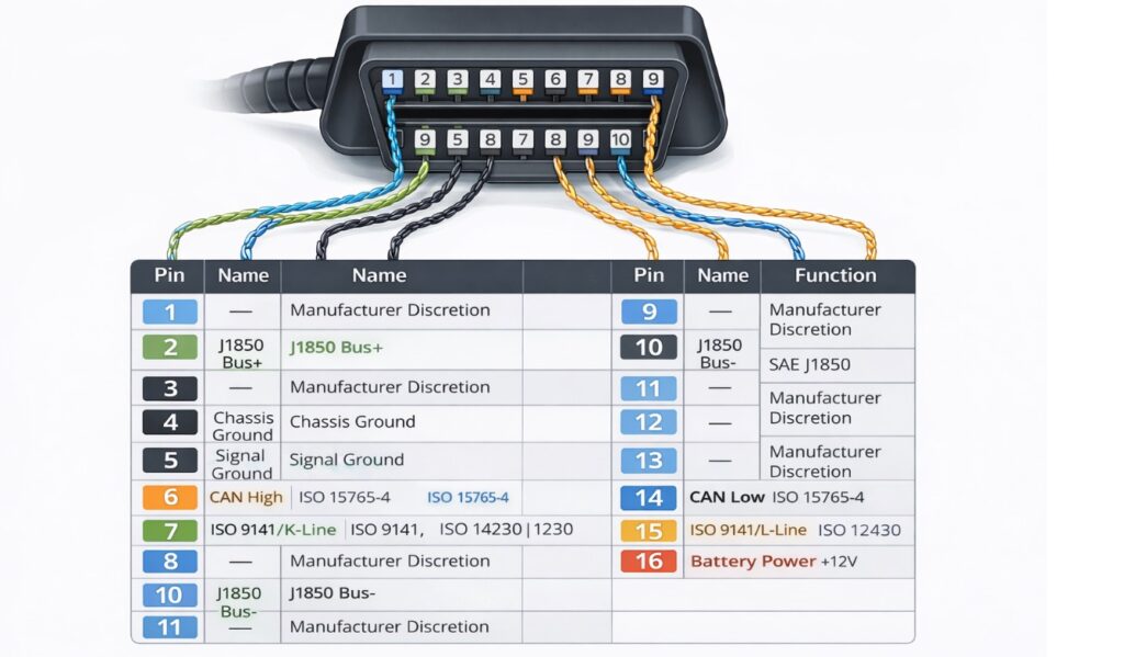
It is a 16-pin connector usually under the dashboard on the driver’s side. So we are using the same obd port 2.
Important pins for CAN Bus on OBD2:
- Pin 6 → CAN High
- Pin 14 → CAN Low
- Pin 16 → Battery +12V (power)
- Pin 4 & 5 → Ground
Most modern vehicles use CAN protocol on these pins (500 kbps speed is very common). If you connect your IndusBoard Coin + TJA1050 to pins 6 and 14, your device can listen to or send messages on the vehicle’s CAN network (but be careful not to disturb important systems).
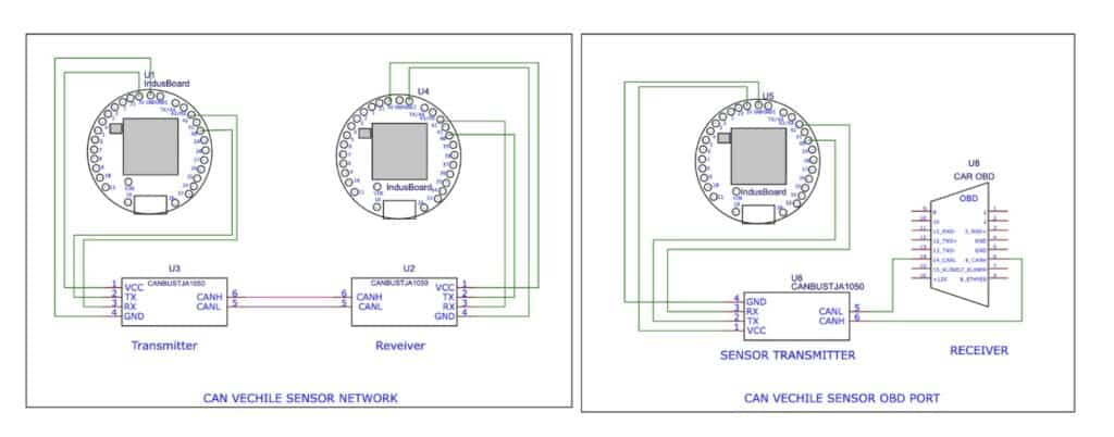
For our design, the Indusboard Coin includes an in-built CAN bus driver. However, to connect it to a vehicle or any external CAN bus network, a CAN transceiver module is required. This transceiver converts the CAN signals to the CAN High and CAN Low wires mentioned earlier, and it is an essential component in any CAN bus network design.
For testing and receiving data, there are two approaches. One option is to build a dedicated CAN receiver using another Indusboard Coin along with a CAN transceiver module, running receiver firmware to read data transmitted by the sensor over the CAN bus. This setup allows you to validate communication without connecting to a real vehicle.
Alternatively, when interfacing with an actual car, CAN bus connectors and the OBD port are required, as shown in Figure 2. The OBD port pins H and L are connected directly to the CAN transceiver’s CAN High and CAN Low pins on the Indusboard, as illustrated in Figure 4 (right circuit). This enables the Indusboard to communicate with the vehicle’s CAN network.
Programming CAN Bus Vehicle Sensor
For this project, we need to prepare two codes: one for the sensor code that sends the sensor data to the CAN bus network of the vehicle, and another for testing the sensor. We also prepare another receiver device that connects to the CAN bus transmitter and displays the received messages.
Transmitter code
In the transmitter code, we configure the RX and TX pins for the CAN bus transceiver module. For each even and sensor, we need to define the node ID so that the receiver can identify and receive a particular message by checking the sensor ID.
Next, we set the function to detect events from the data received for the IMU sensor, such as vehicle acceleration, brake deceleration, speed of acceleration, collision, vacillating accident, and roll of the vehicle due to an accident. Then, we send these events over the CAN bus network with a specific ID.
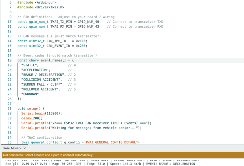
Receiver Code
Now, for the receiver’s code, we need to create the code that will check the incoming data from CANBUS and then display it on the serial monitor.
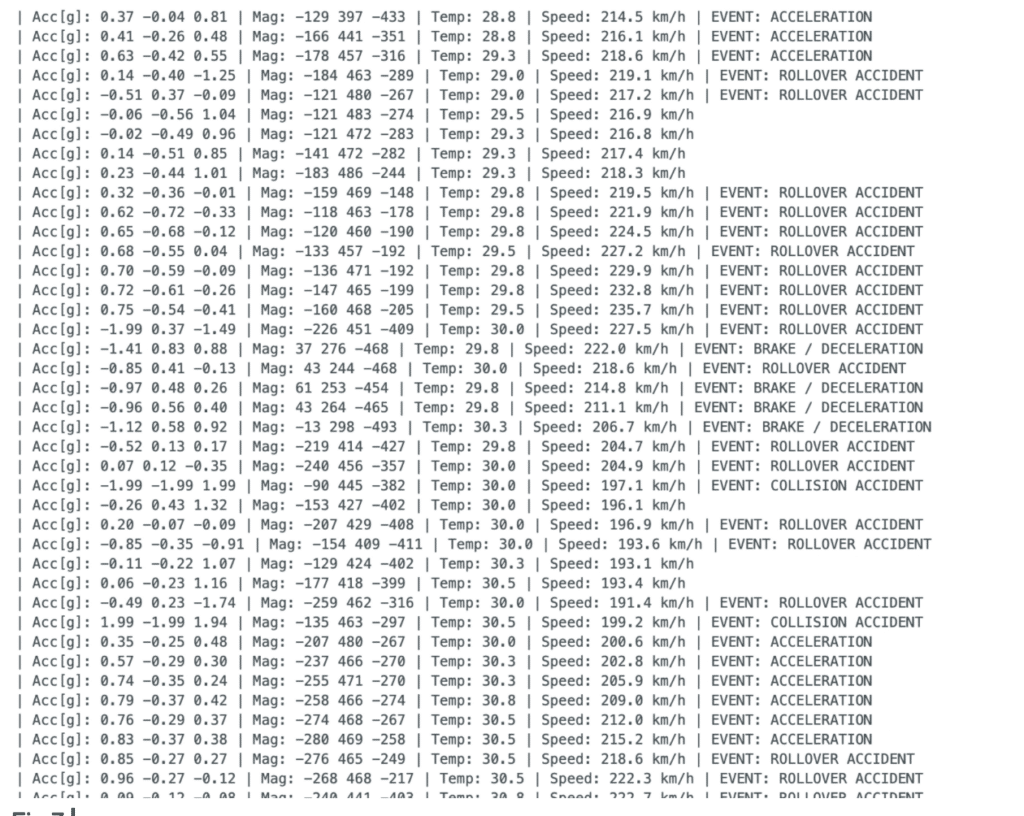
Testing CAN Bus Vehicle Sensor
Now, for testing after connecting the receiver, open the serial port, and you can see the received data from the CAN bus sensor. Now, move the sensor very fast; it will even stop due to acceleration. Or, try to throw it suddenly; the sensor will show the status of collision and accident.
