
This project demonstrates how to build an IoT-enabled CAN bus monitoring system using the Indusboard Coin. While the CAN bus is widely used in automobiles, drones, ships, and other avionics for reliable wired communication, accessing this data wirelessly is often challenging. The proposed design bridges that gap by combining CAN connectivity with built-in Wi-Fi and sensor capabilities.
Automobiles, ships, UAVs, drones, and missiles, among other similar avionics and systems, use the CAN bus for internal communication and management. Many sensors, controllers, and devices communicate and connect together to transmit and receive data at very high speeds with a very complex network of wires. The CAN bus only requires two wires (RX and TX) and can transmit data in its network super simply and easily.
In automobiles, if we want to design a system for ADAS or other vehicle activities, we can use the same. We can simply add our own design sensor and ECU to the vehicle, drone, or missile and monitor them and control them.
However, when it comes to wireless connectivity and monitoring, it becomes a bit difficult because these devices can only be used for wired and internal communication of vehicles. If we want to take that data outside wirelessly, like Wi-Fi, Bluetooth, or the cloud, we need an intermediate board in between.
Here, we do the same. We design a sensor that detects vehicle activities, such as speed, braking acceleration, and collisions and accidents. Using our sensor, we can also send and receive data, acting as both a sensor and a receiver. It can also transmit data and provide you with an IoT dashboard to monitor these vehicle activities in real-time. In this design, we will use the Indusboard coin.
Here, along with CAN bus, we will utilize the IoT capabilities of the Indusboard coin to transmit and update data on the real-time dashboard. Any existing monitor can now track the vehicle’s activity, collisions, accidents, movement usage patterns, and transmission. It was used wirelessly.
Here, the Indusboard coin uses its own inbuilt sensors for magnetic and acceleration measurement for vehicle activity monitoring, along with the coin’s built-in CAN bus and IoT, which easily help in designing the complete system that can be built with IoT connectivity and a dashboard.

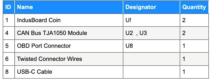
Bill of Materials
Programming IoT CAN Bus Sensor
If you want to learn more about the CAN bus and how it connects to your vehicle, you can read the details in our previous design.
For code similar to our earlier design, we use the accelerometer, magnetometer, and temperature sensor to detect vehicle movement, collisions, accidents, and temperature, as well as many other activities of the vehicle.
After that, we establish the CAN bus connection and send this data to the CAN bus network.
Additionally, it will connect to our phone’s Wi-Fi network and then display this data in real-time.
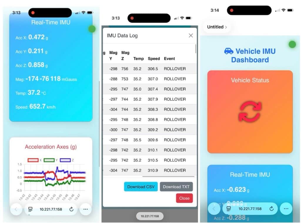
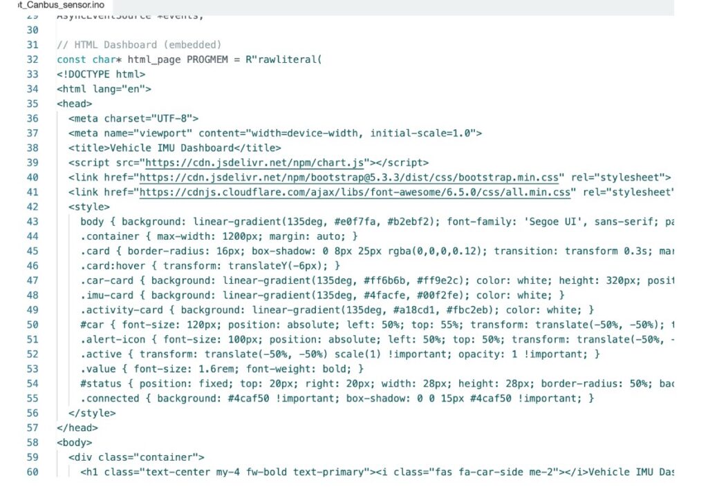
It also allows us to record the data log of vehicle activities like a black box and display them in real-time on the phone. For that, we will create the IoT dashboard using HTML, CSS, and JavaScript.
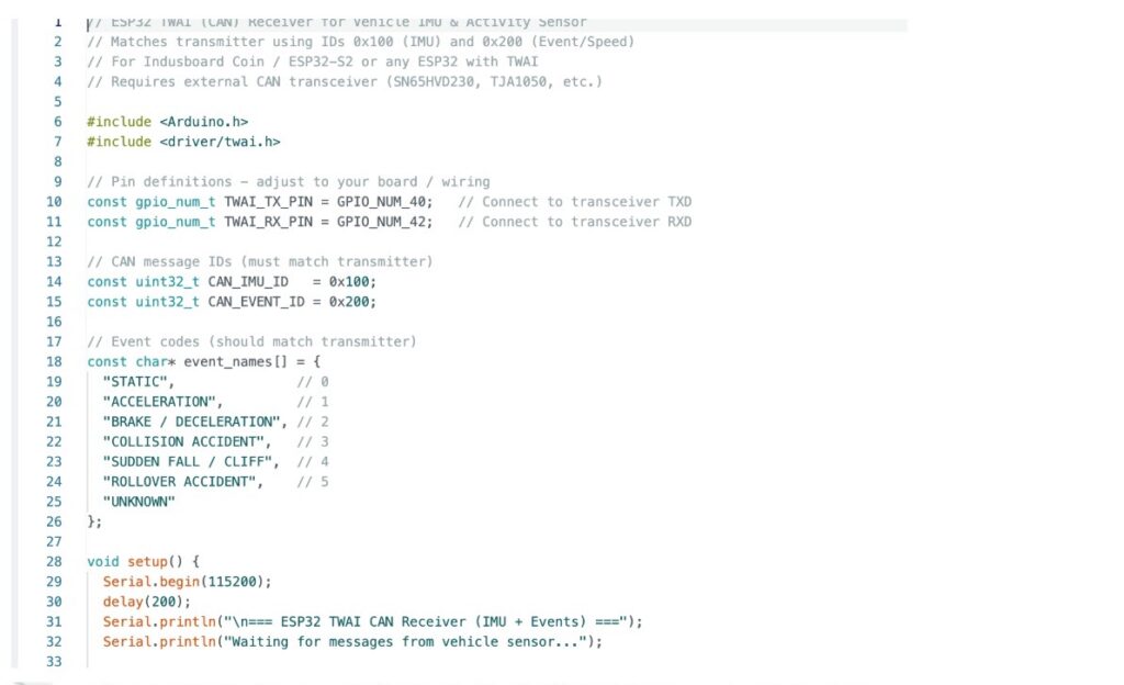
CAN Bus Receiver
Now, to test and verify whether our cannabis network is working and sensing Thai data over the cannabis network, we can also design the cannabis bus receiver using another Indusboard where we can receive the CAN bus data and display it on the USB serial port
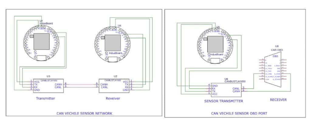
Connection
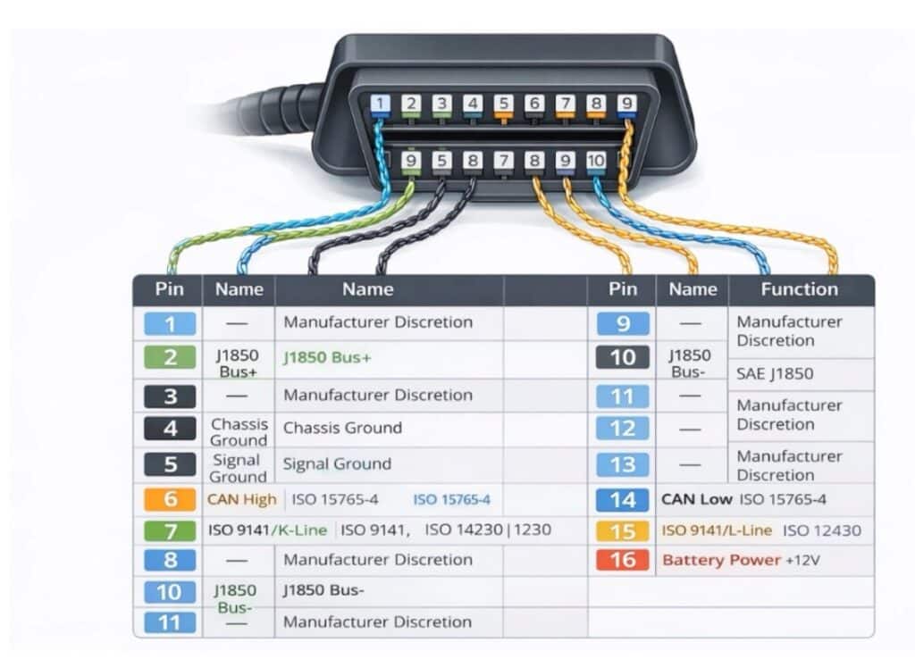
Now, after creating the firm, upload the code to transmit the sensor device and then test it as a CAN bus receiver using another ESP32S2-based board or Indusbaord coin avdn connect them as per the circuit diagram (refer to figure 5). If you want to connect the sensor to an automobile, drone, ship, or any other CAN bus device, use the OBD port and connect it in the right part of the circuit diagram.
For more details on the OBD port and how they work inside drones, missiles, ships, rockets, and how it can connect to the OBD port and pins, you can refer to the earlier article.
Testing IoT CAN Bus Sensor
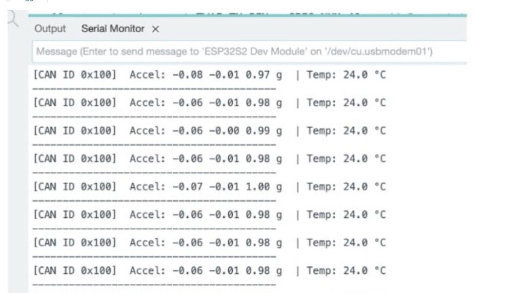
Now, for testing the CAN bus transmission, you can connect the CAN bus receiver device to the serial port as earlier, and you can see the data in the serial monitor.
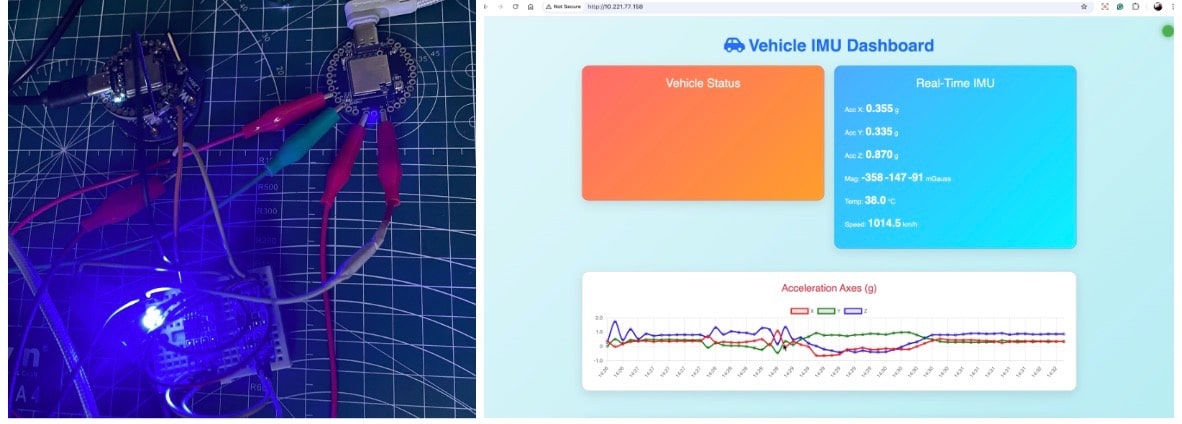
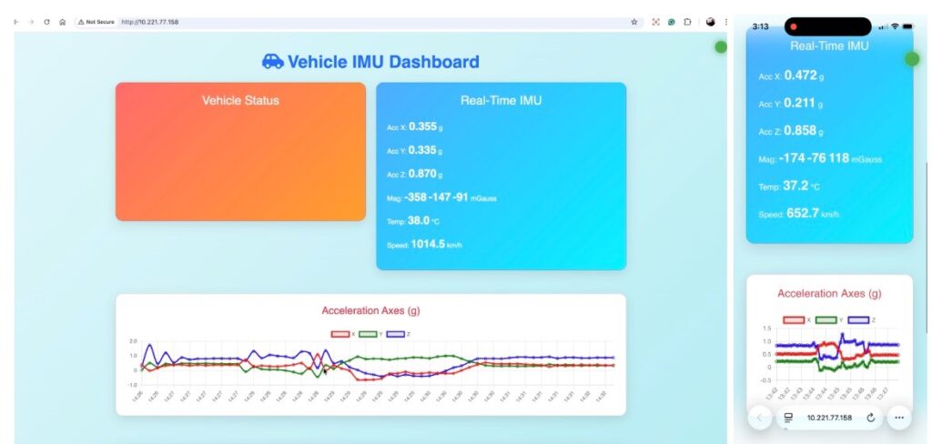
For IoT, connect your phone, laptop, and the same WiFi network that your CAN bus sensor device is connected to. Then, open the browser and search for the device’s IP address to get it.
You can either search for it on an IP scanner or a similar app, or you can also get it from the serial monitor on the Arduino IDE.
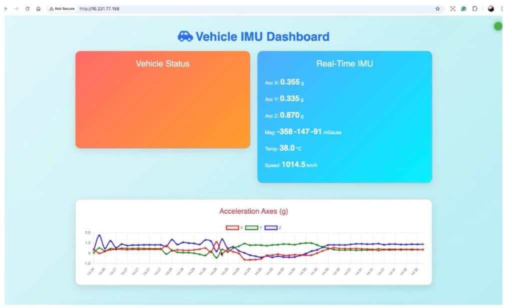
Once you open the dashboard, you can see the real-time graph of vehicle movement, acceleration, on breaks, acceleration speed, and so on. It will display that information on another card. Also, on the vehicle stats part, it will display the volatile status, static, moving, brake, acceleration, collision, accident, vehicle rollover, etc.
More CAN Bus projects:
