
This project describes a high-power solid-state relay (SSR) and AC voltage controller built using a BTA41-1200BW TRIAC (40A, 1200V) and MOC3041 opto-triac. Unlike conventional electromechanical relays or low-current SSRs, the circuit supports up to 40A continuous current and offers two operating modes: phase-angle AC voltage control (dimmer mode) and optically isolated ON/OFF solid-state relay mode.
In voltage-control mode, the circuit uses a DIAC-triggered RC phase-angle control technique to smoothly regulate the RMS output voltage from near zero to full mains level. In relay mode, the optocoupler enables safe microcontroller-based control of high-power AC loads with complete electrical isolation. The design uses a minimal component count, includes a tested PCB prototype, and is suitable for industrial automation, IoT systems, and high-power AC load control.
Relays are essential components in electronic systems and are widely used in IoT and AC-powered applications to control loads using sensor outputs or low-voltage DC signals. Conventional electromechanical relays rely on a mechanical plunger that physically connects or disconnects AC contacts to perform switching.

By contrast, solid-state relays (SSRs) use semiconductor devices to perform switching, enabling faster, silent, and more efficient operation without mechanical wear. An SSR allows current to flow through its control element when an appropriate input signal is applied. While electromechanical relays are limited to simple on/off operation, solid-state relays can also support voltage control and regulation functions. High-current solid-state relays, however, remain relatively uncommon and are typically restricted to a maximum current range of 1A to 10A in commercially available designs.
This system presents a fast-switching, voltage-controlled solid-state relay that surpasses mechanical relays in both switching speed and efficiency. Beyond basic on/off switching, the system supports voltage control, allowing the output voltage to be regulated as required.
Unlike conventional SSRs rated at 10A or 20A, this relay is designed to handle up to 40A of continuous current and to operate at up to 1200V. According to its datasheet, the BTA41-1200BW TRIAC has a 40A continuous current rating and a 1200V voltage rating. The circuit supports two operating modes: one functions as a simple AC power switch, while the other operates as a voltage-controlled switch for output voltage regulation.
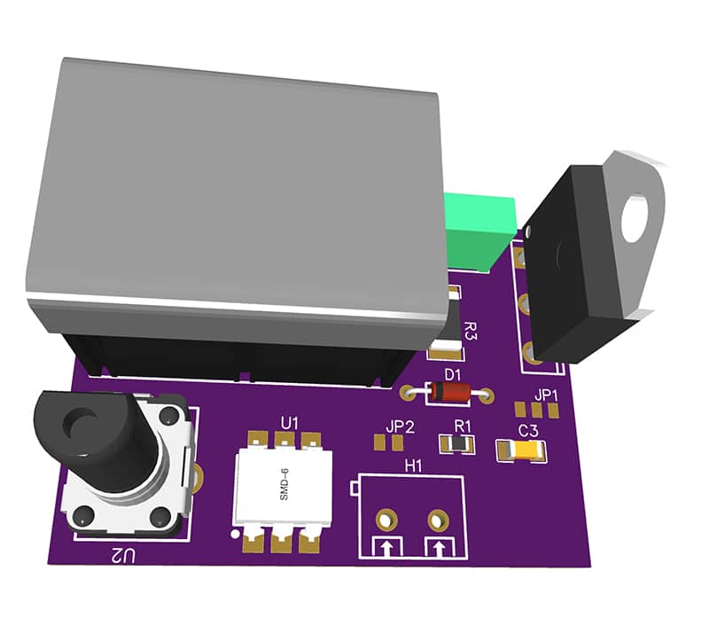
The system employs a minimal set of components, resulting in a compact, straightforward implementation without compromising performance. Fig. 1 shows the prototype PCB used in this system. The components required to assemble the system are listed in the Bill of Materials table.

POC Video Tutorial
| Bill Of Materials | |||||
| Name | Designator | Footprint | Quantity | Manufacturer Part | Manufacturer |
| 100n-400V polyester capacitor | C1 | CAP-TH_L9.5-W4.0-P7.50-D0.6 | 1 | 82CL0114 | KNSCHA |
| KF78C-13.0-2P | C2 | CONN-TH_KF78C-13.0-2P | 1 | KF78C-13.0-2P | KEFA |
| 100nF | C3 | C1206 | 1 | CC1206KKX7RYBB104 | YAGEO |
| DIAC | D1 | DIAC | 1 | ||
| 2-pin terminal connector 40A 800V |
H1 | CONN-TH_2P-P5.00_MX301-5.0-02P-GN01-CU-Y-A | 1 | MX301-5.0-02P-GN01-Cu-Y-A | MAX |
| MOC3041 | IC1 | MOC3041 | 1 | MOC3041M | FAIRCHILD |
| BTA41-1200BW | Q1 | TO-3P-3_L15.3-W4.5-P5.52-L | 1 | BTA41-1200BW | KTP |
| 10kΩ | R1 | R0805 | 1 | 0805W8F1002T5E | UNI-ROYAL |
| 100Ω | R2 | RES-SMD_L6.4-W3.2-R2512 | 1 | SR2512FK-7W100RL | YAGEO |
| Potentiometer 250kΩ-500kΩ | SETPOINT | WH160-1-104 | 1 | Potentiometer WH160-1-104 | JML |
| Heat sink 200-250×120-150 ×70-90 ≤0.5°C/W | U1 | HEATSINK-TH_XSD366-094 | 1 | XSD366-094 | XSD |
You can buy these components from the verified online electronics component suppliers in India.
40A, 1200V Solid-State Relay Circuit and Working
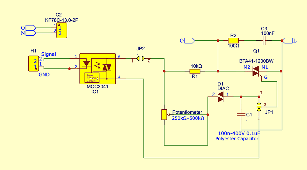
Fig. 2 shows the circuit diagram of the solid-state relay and AC voltage controller. The circuit is built around optotriac MOC3041 (IC1), power TRIAC BTA41-1200BW (Q1), a DIAC (D1), and some discrete components. Since the TRIAC handles high current, a suitable heat sink is mandatory for safe and reliable operation.
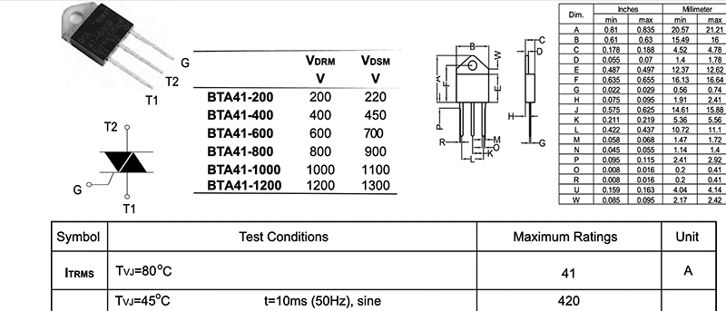
In this circuit, the selected TRIAC is the BTA41-1200BW. As per the manufacturer’s datasheet (see Fig. 3), it can handle load currents of up to 40A and withstand voltages up to 1200V. The BTA41 series is available in several variants with different voltage and current ratings; readers are advised to refer to the datasheet for detailed options. In this system, the high-voltage, high-current variant (40A, 1200V) has been selected to support operation under high-load conditions.
A 250kΩ-500kΩ potentiometer is provided for output voltage control. The MOC3041 optocoupler implements the solid-state relay function and provides optical isolation between the low-voltage control section and the high-voltage AC mains, improving safety and noise immunity.
Voltage Control
The circuit controls the AC output voltage using the phase-angle control technique. The potentiometer, together with the 0.1µF capacitor, forms an RC timing network that determines the charging rate of the capacitor during each half-cycle of the AC input.
When the capacitor voltage reaches the DIAC breakdown voltage, approximately 32V, the DIAC conducts and delivers a sharp trigger pulse to the BTA41 TRIAC gate, turning it on. By varying the potentiometer setting, the TRIAC’s firing angle is adjusted within each AC half-cycle. Fig. 4 shows the integration of the potentiometer into the circuit.
If the TRIAC is triggered late in the half-cycle, only a small portion of the sine wave is applied to the load, resulting in a lower RMS voltage and reduced power. Conversely, if the TRIAC is triggered early, a larger portion of the sine wave reaches the load, producing a higher RMS voltage. In this manner, smooth and continuous control of the AC output voltage, from near zero to full mains voltage, is achieved by adjusting the potentiometer.
The operating range is based on the specifications provided in the manufacturer’s datasheet. The assembled circuit described here was tested using a household power line with a maximum voltage of 260V and a load of up to 30A. Higher voltage and current ranges were not tested. The stated ratings therefore rely on the claims made in the TRIAC datasheet.
How complete circuit work? For clarity, the circuit operation is divided into two modes: dimmer/voltage control mode and solid-state relay mode. Mode selection is determined by jumpers JP1 and JP2.
Also read: Touch-controlled AC Solid-state Relay.
Working in dimmer/voltage Control Mode

Sorry! You cannot read this post further, as this is for EFY PRIME subscribers only.