

Automatic lighting systems are widely used to improve energy efficiency and convenience in residential and commercial applications. The presented auto dusk-todawn LED strip on/off system with timer circuit is designed to control LED strip lighting based on ambient light conditions. It ensures that the lights turn on at dusk (low light) and switch off at dawn (daylight), eliminating manual operation and reducing power consumption.
The circuit uses a light-dependent resistor (LDR) as the primary sensing element to detect changes in ambient light intensity. An operational amplifier functions as a comparator to process the LDR signal and generate a control output. This output drives a transistor stage, which in turn controls a timer IC configured as an astable multivibrator, providing stable switching action with optional delay. The timer function helps prevent flickering or false triggering caused by sudden light variations such as vehicle headlights or passing shadows.
The circuit also incorporates a transistor-based switching mechanism for efficient LED strip drive. It operates from a 12V DC supply, making it suitable for practical installations such as home lighting, garden illumination, signage, and decorative lighting systems. Overall, this system offers a simple, low-cost, and reliable solution for automated lighting with added timing control.
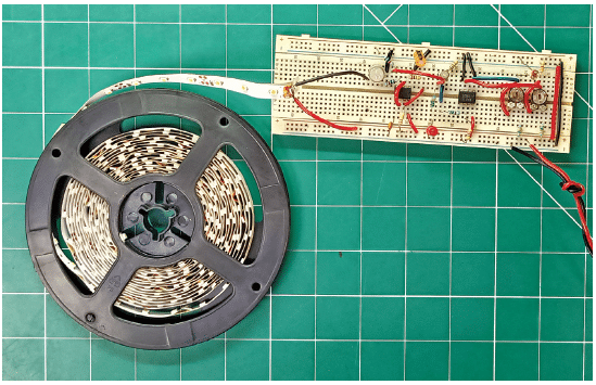
The circuit uses readily available components and can be assembled on a breadboard or a general purpose PCB. Its simple, reliable operation, combined with adjustable timing settings, makes it well-suited for hobbyists, students, and practical lighting automation applications. Fig. 1 shows the prototype assembled on a breadboard.
Circuit and working
Fig. 2 shows the circuit diagram of the auto dusk-to-dawn LED strip on/off system with a timer. It is built around an LDR (light-dependent resistor) to sense ambient light intensity, an LM311 comparator to detect the threshold level (preset voltage), and an NE555 timer to provide a selectable time delay. The LED strip driver transistor T2 is used to safely control a 12V LED strip.
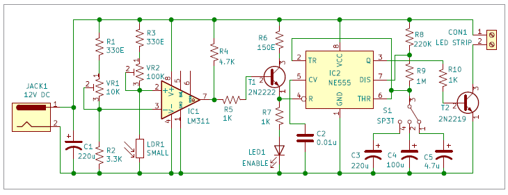
A regulated 12V DC supply is applied through DC jack JACK1. Capacitor C1 filters noise and ripple from the supply. The LDR, together with VR1, VR2, R2, and R3, forms a voltage divider that senses ambient light intensity. Preset VR2 allows adjustment of the light-sensitivity level (the threshold between day and night).
The sensed voltage is fed to pin 2 of IC1 (LM311 comparator). When the ambient light falls below the preset level (set at pin 3 of IC1), the comparator output changes state. Resistor R4 acts as a pull-up resistor for the open-collector output of the LM311, while R5 limits the base current to transistor T1. When transistor T1 conducts, the NE555 timer IC2 receives a voltage at pin 4 (reset pin) and becomes enabled. LED1 serves as an enable indication for IC2. Capacitor C2 stabilises the control voltage pin of the 555 timer against noise.
The time delay is determined by resistors R8, R9, switch S1 (SP3T), and capacitors C3, C4, or C5. Using switch S1, different timing capacitors can be selected to obtain short, medium, or long delay periods. The output of the NE555 at pin 3 drives transistor T2 (2N2219) through base resistor R10. This transistor acts as a power switch for the 12V LED strip connected to CON1.
The circuit’s operation is simple. During daylight, the LDR’s resistance is low, causing the voltage at pin 3 (set by VR2) to remain below the reference voltage at pin 2 (set by VR1). As a result, the comparator output stays low, transistor T1 remains cut off, and the NE555 timer is not enabled. Consequently, transistor T2 also remains cut off, and the LED strip stays switched off.
At night, the LDR’s resistance increases, causing the voltage at pin 3 to rise above the reference voltage at pin 2. The LM311 output goes high, turning transistor T1 on and enabling the NE555 timer. The enable LED (LED1) glows, indicating that the timer is active. The NE555 output goes high/low for a preset duration determined by the selected timing capacitor (C3, C4, or C5) and timing resistors (R8 and R9). During this period, transistor T2 conducts, supplying power to the LED strip, which turns on. After the set delay, the NE555 output goes low, transistor T2 cuts off, and the LED strip turns off. This on/off cycle repeats continuously throughout the night.
The output delay is selected using switch S1, which connects one of the timing capacitors into the circuit. For example, selecting C3 provides a long delay of about 295 seconds (approximately 4.9 minutes), suitable for extended lighting. Choosing C4 gives a medium delay of around 134 seconds (about 2.2 minutes), while selecting C5 results in a short delay of about 6.3 seconds for brief illumination. If a short delay is selected, the LED strip turns on for about 6 seconds after dusk, then turns off for 6 seconds, repeating this cycle throughout the night until dawn.
Thus, the circuit provides three selectable timing intervals, short, medium, and long, enabling automatic switching of the LED strip on/off at dusk with a chosen delay, making it suitable for energy-efficient, unattended lighting applications.
Construction
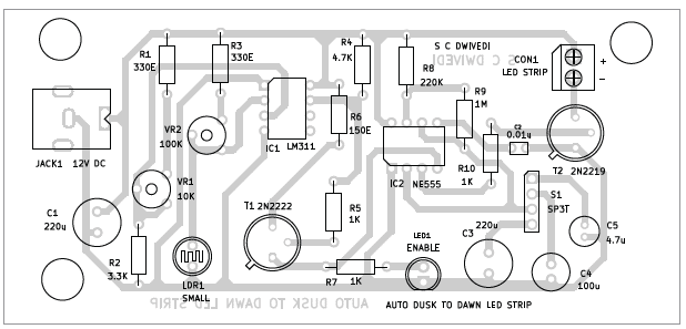
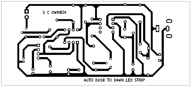
An actual-size, single-sided PCB layout for the auto dusk-to-dawn LED strip on/off with a timer is shown in Fig. 3, and its component layout is shown in Fig. 4. Alternatively, the circuit can be assembled on a high-quality general-purpose PCB if a custom PCB is not available.
Download PCB and Component Layout PDFs: click here
After completing the assembly, calibrate the sensitivity. Power on the circuit and keep the LDR exposed to normal daylight. Slowly adjust the preset VR2 until the LED strip just turns off. Next, cover the LDR by hand or place the unit in a dim environment to simulate darkness. If the LED strip turns on, the threshold is correctly set. Finetune VR2 so that switching occurs exactly at the desired dusk light level. This ensures reliable duskto- dawn operation without false triggering.
Next, test the timer section. With the LDR in dark conditions, select different switch S1 positions (C3, C4, C5). Measure the on-duration of the LED strip using a stopwatch. The delay time should vary with the selected capacitor value (larger capacitance yields a longer delay). If required, minor adjustments can be made by slightly varying R8 or R9 values to obtain the desired timing range. Check for stable operation over several cycles to confirm proper calibration and reliable performance.
Now, mount the assembled PCB inside a suitably sized plastic or ABS cabinet. For user convenience, fix JACK1 (12V DC input jack) and S1 (SP3T time-selection switch) on the front panel of the cabinet. Extend LED1 to the front panel for easy monitoring and label switch S1 for time selection (short/medium/long). After final assembly, connect the LED strip to CON1 with the correct polarity.
After calibration, testing, and final assembly, the unit is ready for installation in corridors, gardens, entry gates, or signboards for automatic dusk-to-dawn lighting control.
Bonus. You can watch the video of the tutorial of this DIY project here.