

Radio has remained one of the most enduring and essential communication devices, retaining its relevance to this day. Its evolution—from large, bulky units to compact, portable forms—has been remarkable. This device pushes that evolution further, delivering one of the smallest wearable and portable FM radios to date.
Two innovative versions have been developed: a watch-style wearable FM radio and another compact enough to fit inside an earbud. The watch-style version is built around the IndusBoard Coin V2, which measures just 3cm in diameter. It features a 3cm GC9A01 round LCD display with a touch interface powered by the CST816S touch driver IC, as illustrated in Fig. 1. The required components for assembling the device are listed in the Bill of Materials table.

The second version is intended to function as a compact FM radio housed directly within an earbud. A prototype of this version will be described in another article soon.

The objective of these designs is to make the FM radio as small and wearable as possible, whether integrated into an earbud or embedded seamlessly behind the IndusBoard. To achieve the latter, the RDA5807M FM stereo radio module has been selected. This article describes the design of the touch display-based compact FM radio. The next article will explore the second version that fits inside an earbud.
| Bill of materials | ||
| Component | Description | Quantity |
| IndusBoard Coin V2 | Main controller | 1 |
| GC9A01 round LCD display | 3cm diameter touch screen | 1 |
| CST816S touch driver IC | For touch embedded on the display | 1 |
| RDA5807M FM Stereo radio module | To receive FM signals | 1 |
| Audio jack/earbud | To listen to the radio | 1 |
| 3.7V Li-Po battery | Portable power supply | 1 |
Software
To begin, several essential libraries must be installed via the Arduino Library Manager, accessible from the tools menu. These include: `TFT_eSPI` for managing the display, `CST816S` for touchscreen control, `RDA5807M` for FM radio functionality, and `TimeLib` for handling clock features.
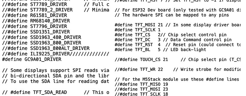
Once the libraries have been installed, the `TFT_eSPI` library must be configured to support the GC9A01 display. This involves navigating to the Documents folder, opening the Arduino directory, accessing the Libraries folder, and locating the `TFT_eSPI` folder within it. Inside it, the `User_Setup.h` file must be opened, and the line corresponding to the GC9A01 display should be uncommented. The SPI pins must then be configured to match the setup on the IndusBoard.
Any available pins on the board may be used. In this case, pins 21, 1, 3, 4, 5, 6, 7, 8, and 9 were used for the display and touch interface. These pin definitions should be correctly reflected in the code. Fig. 2 shows the configuration for the display in the `User_Setup.h` file of the `TFT_eSPI` library.

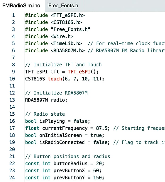
In the source code, the required libraries are included first, followed by the setup for the touchscreen driver. A basic user interface (UI) for the FM radio is then created, featuring three buttons: play/pause and two for changing channels. The code monitors touch coordinates to identify which button is pressed and performs the corresponding action, such as changing the FM frequency or toggling play and pause.
Circuit and working
Fig. 5 shows the circuit diagram of the miniature FM device. It is built around the GC9A01 (MOD1), IndusBoard Coin V2 (MOD2), CST816 touch screen, stereo radio module RDA5807M FM, two speakers (SP1 and SP2), a 3.7V Li-Po battery, and a few other components.

The touch display and FM radio both utilise the I²C protocol for communication, allowing them to be connected either to the same I²C port on the IndusBoard Coin or to separate ports. For simplicity, different ports are used in this setup. The SDA and SCL pins for the touch display are defined in the code and connected accordingly, as shown in the circuit. The touch driver uses hardware I²C pins 8 and 9. The display itself uses SPI and is connected to the IndusBoard’s SPI pins, as defined in the `UserSetup` file earlier.
The IndusBoard Coin V2 provides a 3.3V power supply via the VIN or 3V pin, which powers the GC9A01 display, CST816S touch controller, and RDA5807M FM radio module. A common ground (GND) is shared by all components to ensure proper operation.
Construction
For FM audio output, either an audio jack or speaker can be connected to the speaker audio-out pin. An audio jack is recommended, allowing either earphones or a speaker to be used as preferred. In this device, a speaker with an inbuilt amplifier has been used. Both speakers (SP1 and SP2) are connected to the LOUT and ROUT pins of the RDA5807M to provide stereo audio output.
To assemble this compact wearable FM device, the components are soldered onto the back side of the IndusBoard Coin V2, while the GC9A01 display is mounted on top of the board for clear visibility.
The soldering process begins with preparing the IndusBoard Coin V2. The required pins are identified using the labelled diagram. These include pins such as 3V, GND, TX, RX, and digital pins 1 through 44. The board should be cleaned to avoid soldering issues.
The RDA5807M FM module and CST816S touch controller are soldered onto the back of the board to save space.
For the RDA5807M FM module, pin 5 (SCLK) is connected to IndusBoard pin 5 (SCL), while pin 4 (SDIO) connects to pin 6 (SDA). Pin 2 (GND) is linked to any available ground pin, such as pin 1, and pin 7 (VDD) is connected to a 3V pin, for instance, pin 2. Pins 9 (LOUT) and 10 (ROUT) are soldered directly to the speakers (SP1 and SP2) to enable stereo audio output. A small antenna wire is attached to pin 3 (FMIN) and secured in place to ensure effective signal reception.
For the CST816S touch controller, pin 6 (SCL) is soldered to IndusBoard pin 5, and pin 5 (SDA) is connected to pin 6, sharing the I²C bus with the FM module. Pin 4 (RST) is linked to pin 4, and pin 3 (INT) is connected to pin 3 on the IndusBoard. Ground and power are supplied by connecting pin 2 (GND) to a ground pin and pin 1 (VDD) to a 3V pin. Fig. 6 shows the components soldered with IndusBoard.

FPC integration
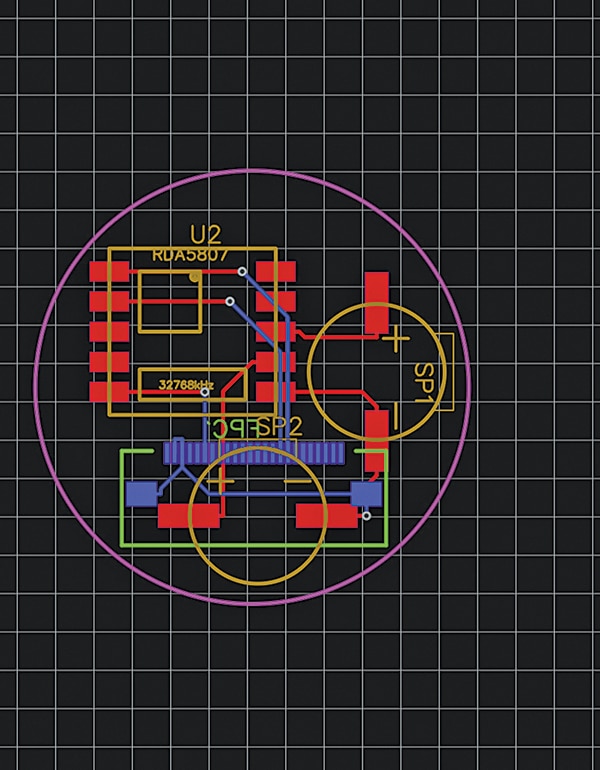
The IndusBoard Coin also supports and hosts its own FPC ecosystem. Custom modules can be designed to integrate seamlessly using the FPC bus. For example, a custom FM radio module can be developed to connect to the IndusBoard Coin via the FPC connector. Fig. 7 shows the double-sided PCB of the project, and Fig. 8 shows the IndusBoard with an FPC connector.
Testing
To test the device, power it using a 3.3V battery and perform the following checks:
Change the FM station using the buttons
The interface displays three touch-sensitive buttons:
• Previous button (left, at coordinates prevButtonX=60, prevButtonY=150): A grey circle with a left triangle and a thin rectangle
• Next button (right, at coordinates nextButtonX=180, nextButtonY=150): A grey circle with a right triangle and a thin rectangle
• Test the previous button:
– Tapping this button decreases the frequency by 0.1MHz (for example, from 87.5MHz to 87.4MHz)
– If the frequency falls below 87.5MHz, it wraps around to 108.0MHz
– The display updates to show the new frequency (for example, ‘87.4MHz’)
• Test the next button:
– Tapping this button increases the frequency by 0.1MHz (for example, from 87.4MHz to 87.5MHz)
– If the frequency exceeds 108.0MHz, it wraps around to 87.5MHz
– The display updates accordingly
Play and pause using the middle button
The middle button is the play/pause button (at coordinates `playPauseButtonX=120`, `playPauseButtonY=150`), with a radius of 30 pixels and a gradient effect (magenta outer ring, purple inner ring).
• Test playback:
– Tap the play/pause button.
– If the radio is paused (`isPlaying=false`), the button shows a play icon (a triangle). Tapping it unmutes the RDA5807M and changes the icon to a pause symbol (two rectangles).
– If the radio is playing (`isPlaying=true`), the button shows a pause icon. Tapping it mutes the RDA5807M and changes the icon to a play symbol.
• Audio output:
– If the RDA5807M is detected (indicated by a green status dot), audio should be audible through the speaker connected to the LOUT/ROUT pins of the RDA5807M when the radio is unmuted.
– Tune to a known FM station (between 87.5 and 108.0MHz) using the previous/next buttons for clear audio output.
– If the RDA5807M is not detected (indicated by a red status dot), the device switches to simulation mode, updating the UI without generating audio.

Debugging and additional checks.
• Using the serial monitor:
– Connect the IndusBoard to a computer via a USB-to-serial adaptor (using TX/RX pins, if available).
– Check for messages like ‘RDA5807M detected’ or ‘RDA5807M not detected, running in simulation mode’ to confirm the radio module’s status.
– Monitor touch coordinates when tapping buttons (like ‘Touch detected – Raw (x, y): (1234, 567) Mapped (x, y): (89, 234)’).
• Touch accuracy:
– If touch buttons are unresponsive or inaccurate, adjust the coordinate mapping in the code accordingly.
The second version of FM radio that fits within an earbud will be published soon.
Bonus. You can watch the video of the tutorial of this DIY project at Link
Ashwini Kumar Sinha, an IoT and AI enthusiast, is Tech Journalist at EFY.