
The article discusses a way of controlling a device (turn ON/OFF) remotely over Internet using an Android Mobile and an ESP32 Wi-Fi module. This assumes that ESP32 is connected to a Wi-Fi router. Thus, the remote device can be accessed from anywhere in the world. Examples are Water Sprinkler in the garden, turning on the air conditioner, turning on the surveillance camera and similar devices.
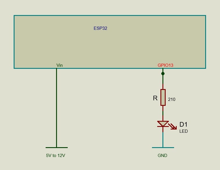
Here, the ESP32 WiFi module is connected to Internet via a WiFi router. One of the Input/Output pins (Pin No.13) is connected to the device through an interface. In this article, we connect a LED in series with a resistor to Pin No.13 (Refer to Fig.1). An Android Mobile is used to switch ON/OFF the LED. ESP32 is a 3.3V device hence the signals are at 3.3V logic.
Parts Required
- ESP32 board 2.4 GHz Dual Mode Wi-Fi – Bluetooth Dual Core with USB cable: 1 no
- LED: 1 no
- 210 ohm: 1 no
Connection Diagram

ESP32 WiFi Module
ESP32 works at 3.3V logic levels. A regulated power between 5V and 12V can be connected to the Vin pin during normal operation. Choose a voltage that is close to 5V, so that power dissipation in the onboard voltage regulator is reduced. During program uploading, the ESP32 can be connected to the Computer using a USB cable. Care should be taken to ensure that both power supplies are NOT given simultaneously. An easy way of powering the ESP32 is by using a power bank that has a USB port.

ESP32 Installation
Connect the ESP32 to the Laptop/Computer using USB cable. Assuming you are on a Windows Machine, Goto Device Manager > Other devices. It will list CP2102 USB to UART Bridge Controller. Right click on it and select Update driver. Follow online suggestions. If this fails, you have to manually install the driver by downloading from the Internet. After installation, Device Manager will show the COM Port to which ESP32 is connected. Note down the COM port number.
In the Arduino IDE, go to Tools > Boards Manager.. and install ESP32 by Espressif System. Go to File > Preferences… In the Additional boards manager URLs: add this link.
This completes the installation of ESP32.
ESP32 code
In our setup, the ESP32 will be working as the Server and our Mobile will try connecting to it. ESP32 will be in STA mode but listening and we have to assign a static IP address. Find out the IP addresses of all the devices connected to the WiFi router and select an IP address that is unused by changing the last octet. This will be our Server’s (ESP32) IP address. Next step is to select the Port number. Select an unused Port number that is between 32767 and 65535.
Connect ESP32 to the computer and open the Arduino IDE. From the Tools menu, select the appropriate ESP32 Board and the COM port. Type in the following code and, compile and upload. Sometimes, you may have to press the BOOT button while uploading. (Remember Arduino programs have to be in a folder with the same name).
// ESP32 in STA mode //

// but listens with static ip //

// Port forwarding to be done //

#include

#define EspPortServ xxxxx // see text //

// Replace with your router credentials

const char* ssid = ".........." ; //

const char* password = "........." ;

WiFiServer server( EspPortServ ); // STA mode //

// ESP32 Static IP address // see text //

// Octet are separated by comma and not dot //

IPAddress localIP( xxx, xxx, xxx, xxx );

IPAddress gateway( xxx, xxx, xxx, xxx );

IPAddress subnet( xxx, xxx, xxx, xxx );

char ch ;

WiFiClient client ;

// LED on GPIO13

int LED = 13;

void setup() {

// Set LED as output

pinMode(LED, OUTPUT);

Serial.begin(115200);

// Configures static IP address : STA mode //

if (!WiFi.config(localIP, gateway, subnet)) {

Serial.println("STA Failed to configure");

}

// Connecting to Wi-Fi //

Serial.println ("ESP32 as Server !");

Serial.print("Connecting to ");

Serial.println(ssid);

WiFi.begin(ssid, password);

while (WiFi.status() != WL_CONNECTED) {

delay(500);

Serial.print(".");

}

// ESP32 Server IP

Serial.println("");

Serial.println("WiFi connected.");

Serial.print ("Server IP address : ");

Serial.println(WiFi.localIP());

server.begin();

}

void loop() {

// ESP32 waits for client //

client = server.available();

if (client) { // when the client connects to ESP32 //

while (client.connected()) {

if (client.available()) {

ch = client.read();

Serial.write(ch); // write to serial monitor //

switch (ch) {

case '1':

digitalWrite(LED, HIGH);

client.print ( "ON" ) ;

break;

case '0':

digitalWrite(LED, LOW);

client.print ( "OFF" ) ;

break;

}

}

}

}

delay (500);

}
This completes the programming of the ESP32 board.
The Android Mobile App
Here, the MIT app inventor platform will be used to develop the App. Create a Google account (or a Gmail account) and log in to
Close the welcome screen. Now the top part of the screen will appear as follows.
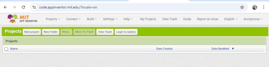
At the top right corner, instead of Anonymous, the Google account name will be displayed. On clicking it the Sign out menu will appear.
Click on New project and give the Project name as Remote_Control. The appearing screen contains four panes, Palette, Viewer, All Components and Properties. In the All Components pane, there is an entry Screen1. It’s properties are displayed in the Properties pane. Change the Title to Remote Control. In the Viewer pane the title will change to Remote Control.
In the Palette pane, click on Layout menu, select HorizontalArrangement and drag it on to the mobile screen displayed in the Viewer pane. In the Properties pane, change AlignHorizontal to Center: 3, AlignVertical to Center: 2, Height to 10 percent and Width to Fill parent. From Palette > User Interface, drag Button and place it inside HorizontalArrangement1 in the Viewer pane. In the All Components pane, select Button1 and rename (using the Rename button at the bottom) it as btn_on. In the Properties pane of btn_on, change FontSize to 16, Height to Fill parent and Width to 30 percent. Again, in the Properties pane, change Text to ON and TextAlignment to center: 1.
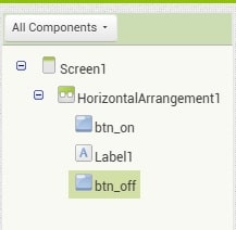
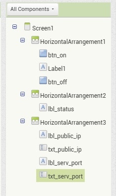
From Palette > User Interface, drag Label and place it on the right side of the ON button inside the HorizontalArrangement1. This is used as a place marker. In the Properties pane of Label1, change Width to 10 percent and make the Text property empty. From Palette > User Interface, drag Button and place it on the right side of Label1. Rename it as btn_off. In the Properties pane of btn_off change FontSize to 16, Height to Fill parent, Width to 30 percent and Text to OFF. The All Components pane will now look as follows.
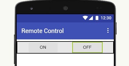
Pay special attention to the relative positions of various blocks. If there is any discrepancy, correct them or redo it until you get it correctly. The Viewer pane will look as follows.
Again, from Palette > Layout drag HorizontalArrangement to the Viewer pane and place it below HorizontalArrangement1. In the Properties pane change AlignHorizontal to Center: 3, AlignVertical to Center: 2, Height to 10 percent and Width to Fill parent. Drag Palette > User Interface > Label and place it inside HorizontalArrangement2. In the All Component pane rename Label2 as lbl_status. In the Properties pane of lbl_status, change FontSize to 16, Text to Not Connected and TextAlignment to center: 1.
Drag Palette > Layout > HorizontalArrangement and place it below HorizontalArrangement2. In the Properties pane, change AlignHorizontal to Center: 3, AlignVertical to Center: 2, Height to 10 percent and Width to Fill parent. Drag Palette > User Interface > Label and place it inside HorizontalArrangement3. Rename it as lbl_public_ip. In the Properties pane, change Text to Public IP: and Text Alignment to left 0. Drag Palette > User Interface > TextBox and place it on the right side of lbl_public_ip. Rename it as txt_public_ip. In the Properties pane, change Width to 30 percent. Drag Palette > User Interface > Label and place it on the right side of txt_public_ip. Rename it as lbl_serv_port. In the Properties pane, change Text to Serv Port: and TextAlignment to right: 2. Drag Palette > User Interface > TextBox and place it on the right side of lbl_serv_port. Rename it as txt_serv_port. In the Properties pane, change Width to 20 percent and TextAlignment to right: 2.
The All Components pane will look as follows.
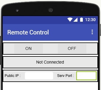
Take care of the relative positions of various items. The Viewer pane will appear as follows.
Now drag Palette > Layout > HorizontalArrangement and place it below HorizontalArrangement3. In the Properties pane, change AlignHorizontal to Center: 3, AlignVertical to Center: 2, Height to 10 percent and Width to Fill parent. Drag Palette > User Interface > Button and place it inside HorizontalArrangement4. Rename it as btn_save. In the Properties pane, change Width to 20 percent, Text to Save and TextAlignment to center: 1. Drag Palette > User Interface > Button and place it on the right side of btn_save. Rename it as btn_close. In the Properties pane, change Width to 20 percent, Text to Close and TextAlignment to center: 1. Drag Palette > User Interface > Button and place it on the right side of btn_close. Rename it as btn_connect. In the Properties pane, change Width to 20 percent and Text to Connect.
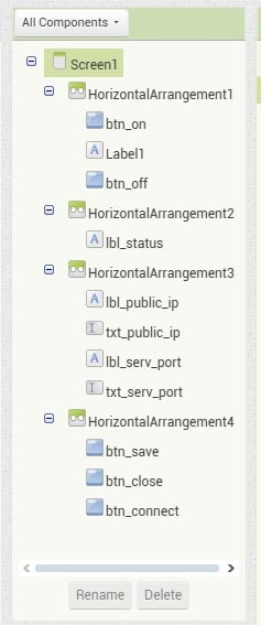
The All Components pane will appear as follows.
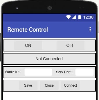
The Viewer pane will appear as follows.
To store the Public IP Address and Server Port Number we will use TinyDB. It is a non-visible component and can store data. Drag Palette > Storage > TinyDB and drop it on the Viewer screen. It will settle at the bottom as TinyDB1.
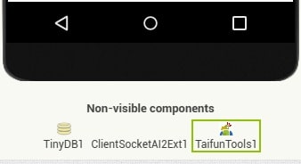
We require two more non-visible components. One is ClientSocketAI2.aix and the other is com.puravidaapps.TaifunTools.aix. Both are to be downloaded from the NET. Save them to a suitable Folder in the Computer. Go to Palette > Extension and click on Import extension. Select the files we saved and Import them. Drag and drop them onto the Viewer screen and they will settle at the bottom as Non-visible components. The bottom of the Viewer screen will appear as follows.
This completes the Designer part of our project.
The Blocks Mode
Log into the App Inventor, if you have already logged out. At the Top – Right corner of the screen, below your Google id, you can see two buttons, Designer and Blocks. Up to now we have been working in the Designer mode. Now click on the Blocks button.
The screen consists of two parts – Blocks and Viewer. Note the Vertical Scroll Bar on both sides. Have a look at the full content of the Blocks pane by moving the scroll bar. Clicking on any item in the Blocks pane, a set of blocks will appear which can be dragged to the Viewer pane. In the Viewer pane, we match various blocks to make a program.
First, we need to create two variables, one for holding the Public IP address and the other for holding the Server Port Number.
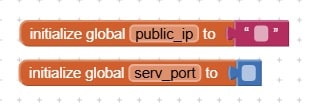
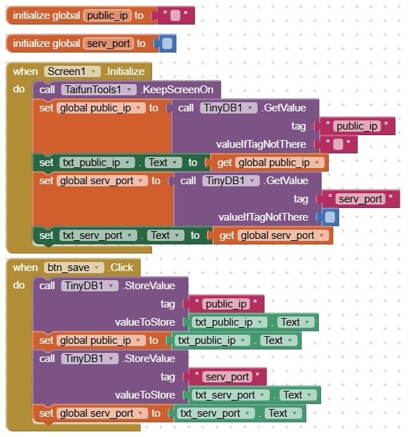
Click on Blocks > Built-in > Variables and drag the initialise global name to block to the Viewer pane. You can see that there is an open end to which we can connect other blocks. In this, name is the name of the variable. Rename it to public_ip. Click on Blocks > Built-in > Text and drag the empty box (top most one) to the Viewer pane and mate it at the open end (look at the images given below). Again, click on Blocks > Built-in > Variables and drag the Initialise global name to block to the Viewer pane. Rename name to serv_port. This time click on Blocks > Built-in > Math and drag the block containing 0 (top most one) and mate it at the open end. Remove the 0 from the block. The Viewer pane will appear as follows.
We use the TinyDB (a small database) to save the IP address and the Port number, so that, we don’t have to type it again when we reopen the App. In this IP address is a string and Port number is a numeric value.
Click on Blocks > Screen1 and drag when Screen1. Initialise block to the Viewer screen. The scroll bar can be used to see the items at the bottom. Click on Blocks > Screen1 > TaifunTools1 and drag call TaifunTools1.KeepScreenOn and mate it with when Screen1. Initialise block as shown in the figure (see below). Bring your Mouse cursor over the variable name public_ip in the initialise global public_ip to block in the Viewer screen. This will produce two blocks. Select set global public_ip to block and place it below the call TaifunTools1.KeepScreenOn block. Click on Blocks > Screen1 > TinyDB1, drag call TinyDB1.GetValue block and mate it at the open end. Click on Blocks > Built-in > Text, select the empty block and mate it at the open end. In this block type the variable name public_ip. Click on Blocks > Screen1 > > txt_public_ip, drag set txt_public_ip.Text to and place it at the bottom. Place Mouse cursor on public_ip in initialise global public_ip to block in the Viewer screen, select get global public_ip block and mate it at the open end.
Place Mouse cursor over serv_port in the initialise global serv_port to block, select set global serv_port to block and place it below the previous block as shown in the figure. Click on Blocks > Screen1 > TinyDB1, select call TinyDB1.GetValue and mate it at the open end. From Blocks > Built-in > Text, take the empty block and mate it at the open end. In the empty block type serv_port. Remove the empty string block against the valueIfTagNotThere caption. From Blocks > Built-in > Math, drag the top most block (which contains 0) and mate it at the open end. Remove the 0 from the block. There is a recycle bin at the right-bottom corner. Any unused block can be put in it.
Click on Blocks > Screen1 > > txt_serv_port, drag set txt_serv_port.Text to block and place it at the bottom. Place Mouse cursor on serv_port in the initialise global serv_port to block in the Viewer screen, drag the get global serv_port block and mate it at the open end. The diagram is shown below.
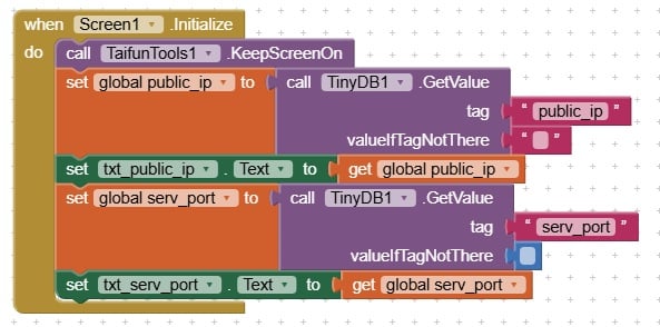
This will read from the Database and initialise the variables, provided we have saved it. In the next part we discuss how to save the values in TinyDB.
Click on Blocks > Screen1 > > btn_save. Drag when btn_save. Click to the Viewer screen. From Blocks > Screen1 > > TinyDB1, drag call TinyDB1.StoreValue and mate it with when btn_save.Click block. From Blocks > Built-in > Text, drag the empty block and mate it at the open end against tag. From Blocks > Screen1 > > txt_public_ip drag txt_public_ip.Text block and mate it at the other open end. Bring the Mouse cursor over public_ip in the initialise global public_ip to block, drag set global public_ip to block and place it at the bottom. See the figure. From Blocks > Screen1 > > txt_public_ip, drag txt_public_ip.Text and mate it at the open end.
Repeat the above procedure for the serv_port as shown in the diagram.
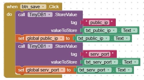
When we press the Save button, the Public IP address and the Port number will be saved to memory.
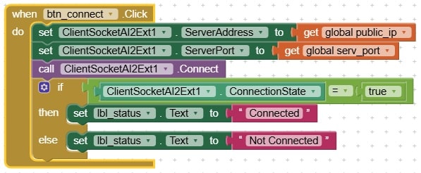
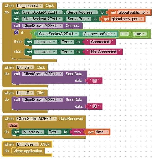
Next, we will see how we can connect to the Internet. From Blocks > Screen1 > > btn_connect, drag when btn_connect. Click block to the Viewer screen. From Blocks > Screen1 > ClientSocketAI2Ext1, drag set ClientSocketAI2Ext1.ServerAddress to block and mate it. Place Mouse cursor on public_ip in initialise global public_ip to block, drag get global public_ip block and mate it at the open end. From Blocks > Screen1 > ClientSocketAI2Ext1, drag set ClientSocketAI2Ext.ServerPort to block and place it at the bottom. Place Mouse cursor over serv_port in initialise global serv_port to block, drag get global serv_port block and mate it at the open end. Click on Blocks > Screen1 > ClientsocketAI2Ext1, drag call ClientSocketAI2Ext1. Connect the block and place it at the bottom.
Checking whether connecting is successful.
Click on Blocks > Built-in > Control, drag if then else block and mate it at the bottom. From Blocks > Built-in > Logic, select the block containing the “=” sign and two place holders, and mate it at the open end against if. In this, there are two place holders. Click on Blocks > Screen1 > ClientSocketAI2Ext1, drag ClientSocketAI2Ext1.ConnectionState to fill the first placeholder. From Block > Built-in > Logic, drag the true block and fill the second place holder. From Blocks > Screen1 > > lbl_status, drag set lbl_status.Text to block and mate it against then. From Blocks > Built-in > Text, drag the empty block and mate it at the open end. Insert the word Connected in the empty block. Repeat the same for the else open end but change the word to Not Connected. The diagram is given below.
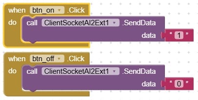
The remaining blocks are very simple. We have to implement the functionality for the ON/OFF buttons.
Click on Blocks > Screen1 > > btn_on and drag the when btn_on.Click block to the Viewer screen. From Blocks > Screen1 > ClientSocketAI2Ext1, drag call ClientSocketAI2Ext1. SendData block to mate inside the when btn_on.Click block. From Blocks > Built-in > Text, drag the empty block and mate it at the open end. In the empty block type 1.
Click on Blocks > Screen1 > > btn_off and drag when btn_off.Click block to the Viewer screen. Repeat the above procedure for this block also. Insert 0 in the empty block.
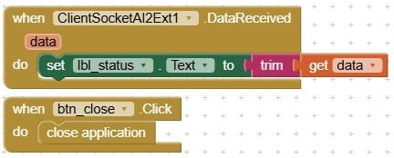
Two more blocks to be done. From Blocks > Screen1 > ClientSocketAI2Ext1, drag when ClientSocketAI2Ext1.DataReceived to the Viewer screen. You can see that there is a variable data that stores the received data. Click on Blocks > Screen1 > > lbl_status, drag set lbl_status.Text to block and place it inside as shown. From Blocks > Built-in > Text, drag trim block and place it at the open end. Bring the Mouse cursor on data, select get data block and place it at the open end.
Click on Blocks > Screen1 > > btn_close and drag when btn_close.Click block on to the Viewer screen. On the Viewer screen, at an empty space type close application and press enter. This will produce a block, drag it and place it inside the when btn_close.Click block.
The complete diagram is shown below as two parts.
Installing the App on an Android Mobile
The following method works only if both the Mobile and the Laptop/Computer are on the same WiFi. In the Mobile, go to Play Store, download and install MIT AI2 Companion. In the Laptop log into MIT App Inventor. At the top there is a menu named Build with a submenu, Android App (.apk). Click on it. Now the App Inventor will start compiling. After compilation, it will display a QR code. Take your Mobile and open MIT AI2 Companion. Using the Scan QR code button, scan the QR code. Follow the instructions and the App will get installed in your Mobile. Open the App using the icon. Your screen will appear as follows.
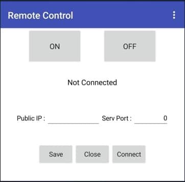
Fill the Serv Port: with the port number used in the ESP32 program. The Public IP: can be obtained by typing whatismyip.com in a browser. Fill the IPv4 address in the Public IP column and press Save. The Public IP address will change every time you reboot the router. (Note: Keep your IP address and Port number a secret for security reasons). You can press the Connect button to connect to the ESP32 Server.
Port Forwarding
The Public IP address we obtained is really that of the router. So, when it receives a request, it should know where to forward this request. This is done by Port Forwarding. Here, how to setup port forwarding in the NETLINK HG323DAC modem will be discussed. Other routers will have a similar procedure. In case of doubt, Google the internet.
Open a browser and type 192.168.1.1. This brings up a screen.
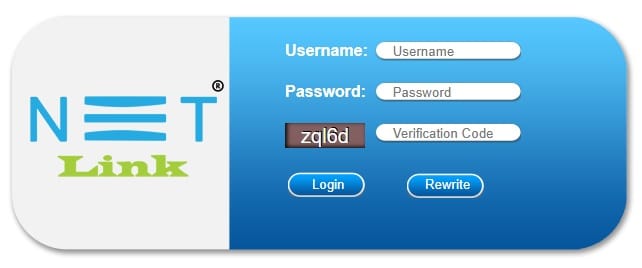
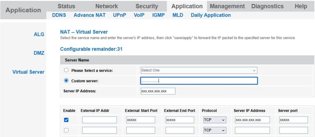
Give the Username, Password and the verification code. Press Login. Click on Application > Advance NAT > Virtual Server > Add. Select Custom server and give a name. In the Server IP Address column, give the local IP address of the ESP32 server. Check the Enable check box. Ignore the External IP address column and fill both External Start Port and External End Port with the ESP32 port number. The protocol is TCP and fill the Server IP Address (ESP32 IP address). Server port is the ESP32 listening port number. Press the Save/Apply button. A screenshot is given below.
Now, click on DMZ option. Check the Enable radio button and enter the local IP address of the ESP32 as the DMZ Host IP Address. Click the Save/Apply button. Logout from the screen.
Our system is ready for testing. Connect the ESP32 (already programmed) to a power source (may be a power bank). Open the app on your mobile and fill in the Public IP address and the Port number. Press Connect. If successful, the Connected message will appear. Press the ON button and the LED will light up. Press the OFF button to switch of the LED.
Thus, you can turn an LED ON and OFF from anywhere in the world.
Remarks
Every time you reboot the Router, you have to re-enter the IP address in the mobile screen. You can purchase a static IP address so that this step can be avoided. We can periodically check for internet connectivity and if lost a message can be displayed in the status field. For the sake of simplicity, this has been omitted.